The installation of such sensors at every electrical using object with traditional systems can be both costly and highly invasive for a large enterprise.
Home technologies generally have yet to penetrate many industries and commercial establishments.
Sectors like healthcare, in which the typical facilities of the sector (i.e. hospitals, clinics) can be classified as high-activity facilities with large numbers of assets to be monitored, can be problematic.
Specifically, the lack of connected technology in such facilities is often driven by a couple of concerns.
The first is the invasiveness of installing and expanding networks of devices within the physical building.
Disruption of power systems for technology installation can cost more immediately than the long term
gain the technology can offer.
For example, a hospital generally cannot afford to shut off its
electricity (even to a relatively small portion of the facility) without having to render that portion completely unusable for its primary task while the installation occurs.
This can result in thousands of lost hours of work.
A second problem is that the large number of assets to be monitored can make the number of needed sensors (assuming at least one needs to be provided to virtually every asset) cost prohibitive.
Though effective, these methods do not scale appropriately to high draw buildings in which such devices would be very costly and disruptive to install.
In order to achieve appropriate positioning, massive and invasive installation within a facility has previously been necessary to place the physical nodes within the network, provide power to said nodes, and connect said nodes in a communications network.
This process is
time consuming, must be conducted by a trained
technician, and requires at least part of the facility to disconnect electrical power.
While effective for monitoring high value assets such as company vehicles, GPS transceivers are expensive, power intensive, and are generally substantially less effective indoors as
satellite signals may not achieve sufficient accuracy.
As most commercial facilities are indoors, GPS technologies are generally not cost effective for
asset tracking within facilities.
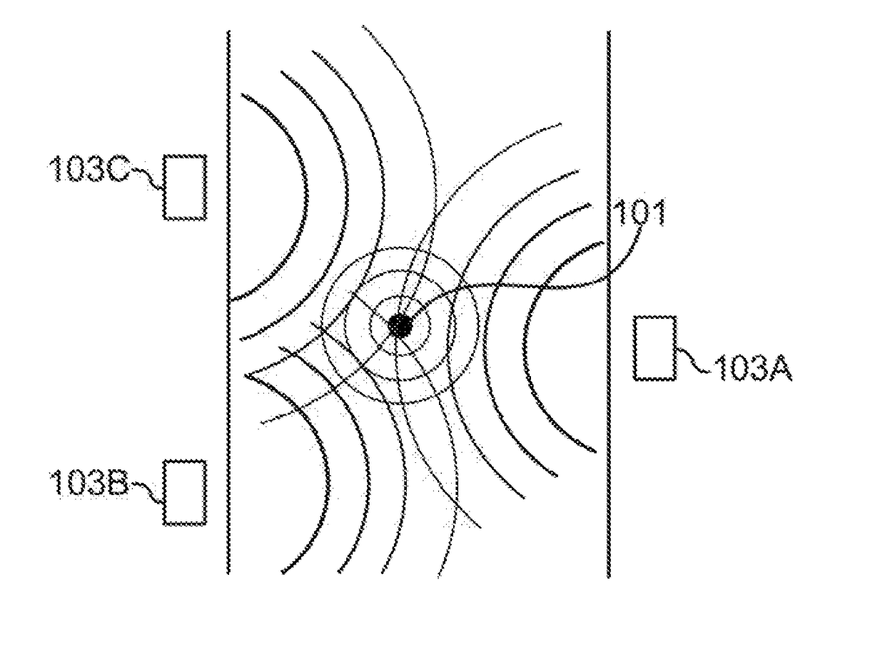
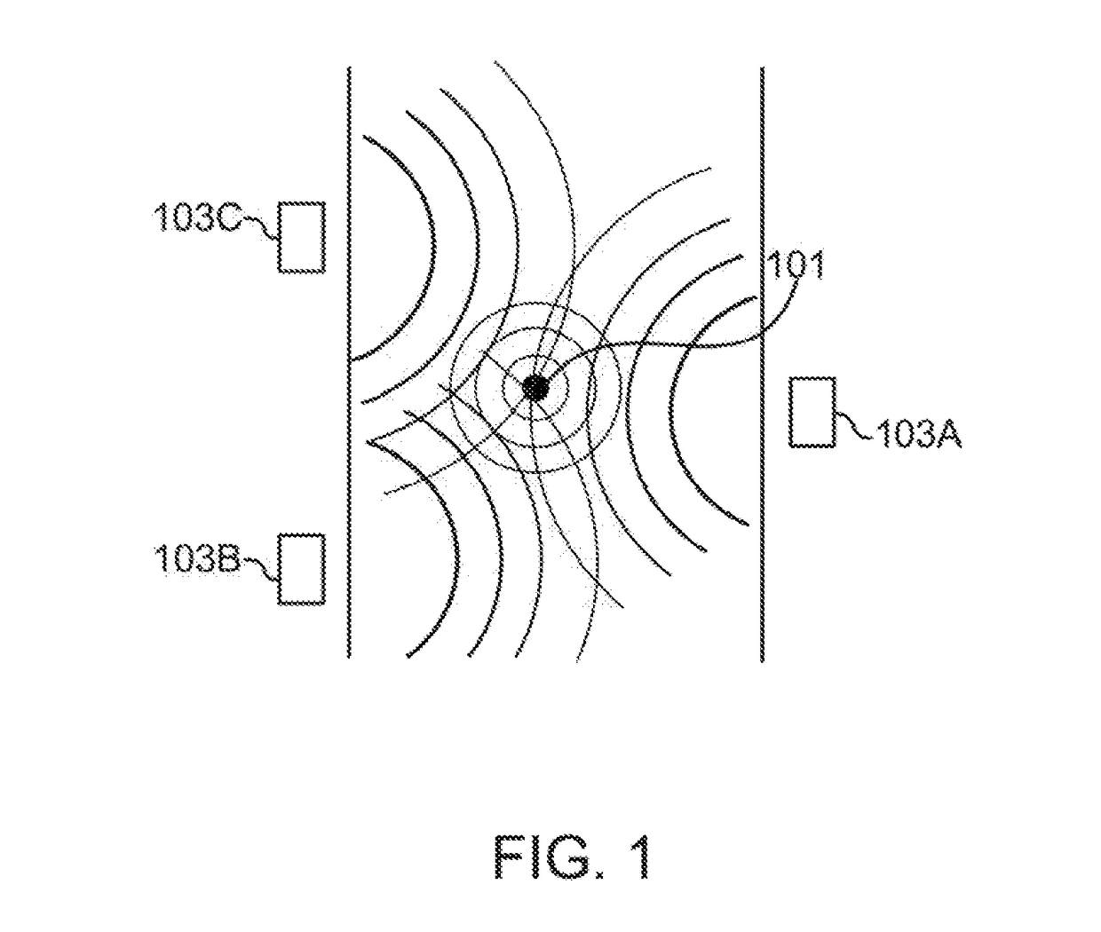
A problem with the
layout of FIG. 1, however, is that a
high density of beacons (103A), (103B), and (103C) is required to aggregate accurate and useful information about an environment from these systems.
Further, each of these beacons has traditionally had to be mounted or placed somewhere where it won't be in the way and won't be moved or damaged by standard activities, and it requires connection to a power source to power its activities which can result in disruption during installation.
This can be a serious problem in facilities such as hospitals that rely on
distributed power outlets throughout the facility for other purposes.
Overall, all of these problems contributes to
beacon systems involving an expensive and invasive installation process for each sensor which potentially includes disruption of main electrical power for safety reasons during installation.
This presents many of the same problems as installation of power monitoring systems in those same facilities.
Thus, while both technologies are clearly desirable for use with commercial facilities, difficulties in installation have led to relatively low adoption.

