
Connector Terminal

a technology of connecting terminals and connectors, applied in the direction of connecting, electrical equipment, coupling contact members, etc., can solve the problems of easy corrosion progress, extremely low corrosion resistance of fe or fe-based alloys, etc., and achieve the effect of improving corrosion resistance and low corrosion resistan

Inactive Publication Date: 2017-11-09
AUTONETWORKS TECH LTD +2
View PDF13 Cites 7 Cited by
  • Summary
  • Abstract
  • Description
  • Claims
  • Application Information

AI Technical Summary

Benefits of technology

[0004]In recent years, a connector terminal has been desired which has a higher rigidity and can reduce material cost for miniaturization and cost reduction. Accordingly, it is considered to use Fe or Fe-based alloy having a high material strength and a low material cost as a metal base material for the connector terminal. In this case, it is effective to form a plating film such as a Sn plating film on a surface of Fe or Fe-based alloy as before in order to improve connection reliability.
[0005]By the presence of the above plating film, corrosion resistance can be maintained in most parts of the connector terminal. However, Fe or Fe-based alloy has an extremely low corrosion resistance as compared to brass and the like. Thus, the connector terminal of this type has a problem that corrosion easily progresses even by slight exposure of the metal base material.
[0006]The present design was developed in view of the above background and aims to provide a connector terminal capable of improving corrosion resistance even if a metal base material is made of Fe-based alloy.
[0008]In the above connector terminal, even if the metal base material is made of the above Fe-based alloy, the surface of the base material exposed part formed by exposing the metal base material is covered by the coating film made of the anti-rust oil. Thus, in the above connector terminal, direct contact of the base material exposed part having a low corrosion resistance and moisture is made difficult by the coating film and corrosion resistance can be improved.

Problems solved by technology

However, Fe or Fe-based alloy has an extremely low corrosion resistance as compared to brass and the like.
Thus, the connector terminal of this type has a problem that corrosion easily progresses even by slight exposure of the metal base material.

Method used


Image

  • Connector Terminal
  • Connector Terminal
  • Connector Terminal

Examples


embodiments

[0024]Hereinafter, connector terminals of embodiments are described using drawings.

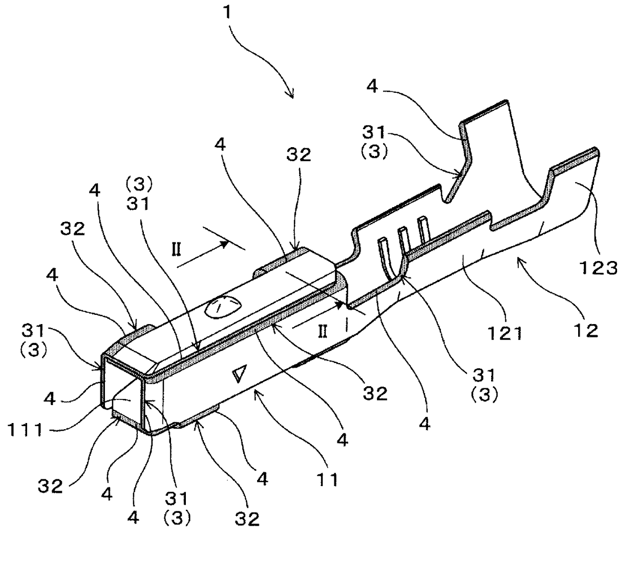
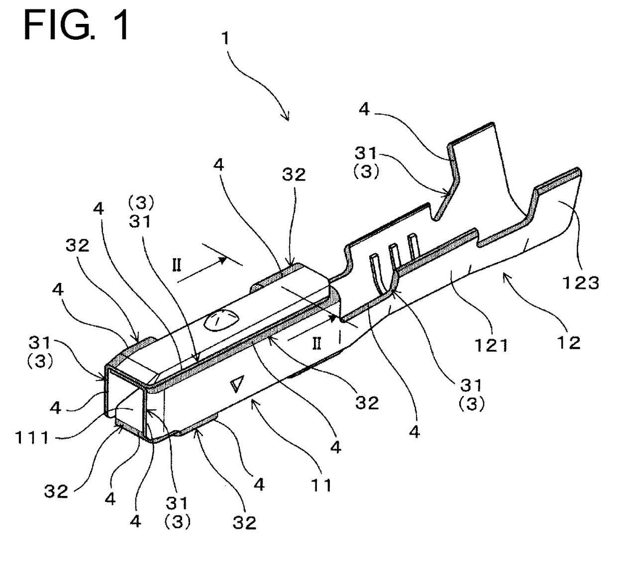
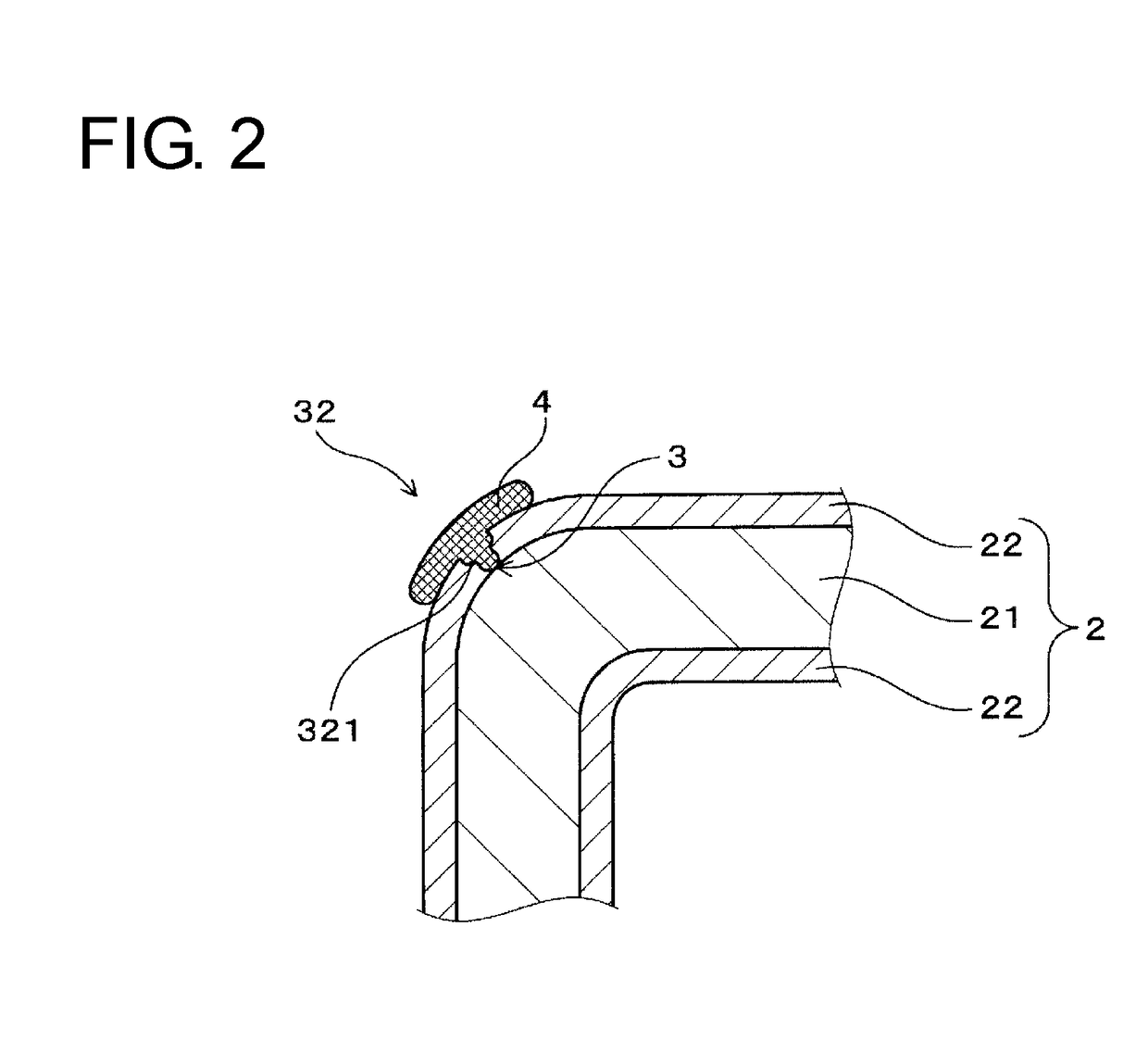
[0025]A connector terminal of a first embodiment is described using FIGS. 1 and 2. As shown in FIGS. 1 and 2, the connector terminal 1 is made of a terminal material 2 including plating films 22 on surfaces of a metal base material 21.

[0026]In this example, the connector terminal 1 is specifically a female terminal as shown in FIG. 1 and used for a connector (not shown) of a wiring harness for automotive vehicle. More specifically, the connector terminal 1 includes a fitting portion 11 in the form of a rectangular tube and a barrel portion 12 connected to the fitting portion 11.

[0027]A tab portion of a male terminal (not shown) as a mating terminal to be electrically connected is inserted into the fitting portion 11. A resilient contact piece 111 is formed inside the fitting portion 11 by folding a base plate portion of the fitting portion 11 inwardly and rearwardly. The resilient contact piece 111 is...


PUM


Abstract

A connector terminal capable of improving corrosion resistance even if a metal base material is made of Fe or Fe-based alloy. The connector terminal is made of a terminal material including a plating film on a surface of the metal base material. The metal base material is made of Fe or Fe-based alloy. The connector terminal includes a base material exposed part formed by exposing the metal base material and a coating film made of anti-rust oil and covering a surface of the base material exposed part. The base material exposed part can be present at a punched fracture surface formed by punching the terminal material and / or at a bent portion formed by bending the terminal material.

Description

CROSS REFERENCE TO RELATED APPLICATIONS[0001]This application claims the priority of Japanese patent application JP2014-234519 filed on Nov. 19, 2014, the entire contents of which are incorporated herein.TECHNICAL FIELD[0002]The present invention relates to a connector terminal.BACKGROUND ART[0003]Conventionally, connector terminals having various shapes are used in connectors used in vehicles such as automotive vehicles. A connector terminal is generally made of a terminal material including a Sn plating film on a surface of copper alloy such as brass in many cases (see patent literature 1 JP2012-185984).SUMMARY[0004]In recent years, a connector terminal has been desired which has a higher rigidity and can reduce material cost for miniaturization and cost reduction. Accordingly, it is considered to use Fe or Fe-based alloy having a high material strength and a low material cost as a metal base material for the connector terminal. In this case, it is effective to form a plating film...

Claims


Application Information

Patent Timeline
IPC IPC(8): H01R13/03
CPCH01R13/03H01R4/184
Inventor NATSUME, TAKASHIFURUKAWA, KINGOSATOU, MIKIO
Owner AUTONETWORKS TECH LTD
Learn More