Ceramic filter

Active Publication Date: 2006-09-28
NGK INSULATORS LTD
View PDF4 Cites 26 Cited by
  • Summary
  • Abstract
  • Description
  • Claims
  • Application Information

AI Technical Summary

Benefits of technology

[0017] The present invention has been made in order to solve the above-mentioned problems of the prior art and provides a ceramic filter which can effectively prevent the erosion of the base body and filter me

Problems solved by technology

In recent years, worldwide water shortage and problems caused by pathogenic microbes including Cryptosporidium and 0-157 have become serious.
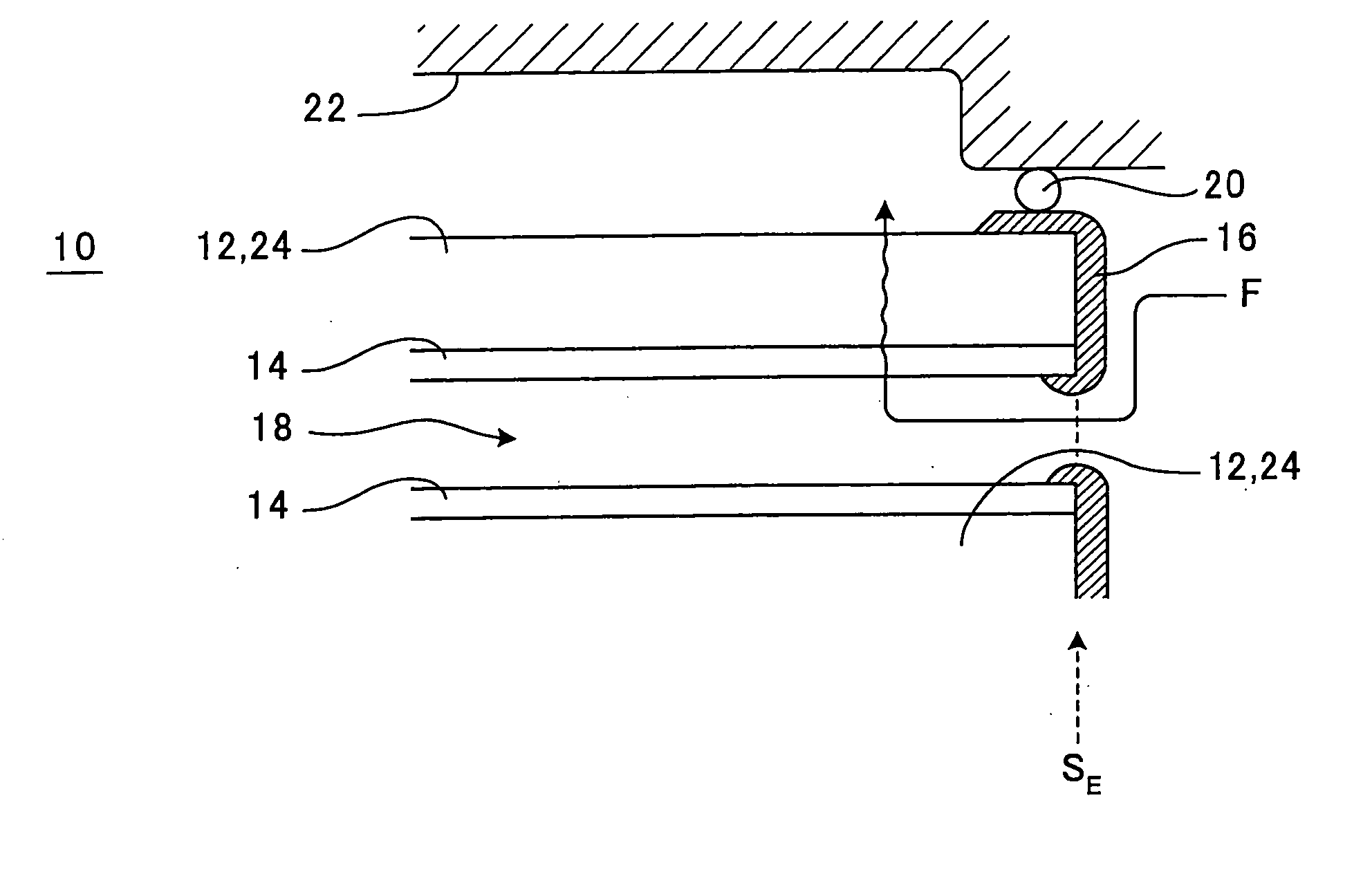
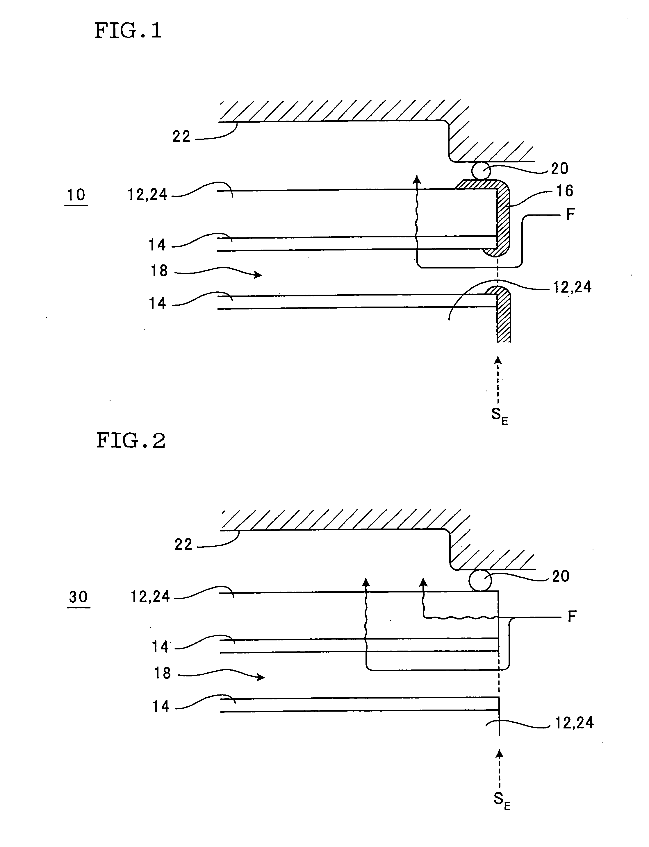
In a ceramic filter having such a structure, there is a fear that not only intended filtration is impossible but also mixing of to-be-treated fluid F into treated fluid after permeation through filter membrane 14 invites contamination of the treated fluid after permeation.
In the membrane separator described in the Patent Literature 1, however, the base body and filter membra

Method used


Image

  • Ceramic filter
  • Ceramic filter

Examples


examples

[0073] The ceramic filter of the present invention is described specifically below by way of Examples. However, the Examples indicate some of the embodiments of the present invention and the ceramic filter of the present invention should not be interpreted based only on these Examples.

[Base Body]

[0074] In Examples and Comparative Examples, a base body constituted as follows was used as the base body of ceramic filter. The base body was a tubular base body of 10 mm (outer diameter), 7 mm (inner diameter) and 500 mm (length), made of an alumina porous material having an average pore diameter of 10 μm as measured by mercury porosity.

[0075] The base body was produced as follows. At first, to 100 parts by mass of alumina particles (as aggregate particles) having an average particle diameter of 50 μm was added 20 parts by mass of frit (as a sintering aid). Further, water, a dispersing medium and a thickener were added, followed by mixing and kneading, to obtain a puddle. The puddle was...


PUM

PropertyMeasurementUnit
Fractionaaaaaaaaaa
Fractionaaaaaaaaaa
Fractionaaaaaaaaaa

Abstract

A ceramic filter has (A) a base body having partition walls made of a ceramic porous body, wherein cells 18 are defined by the partition walls, (B) filer membranes provided on the partition walls, made of a ceramic porous body having an average pore diameter smaller than that of the surface of each partition wall, and (C) a glass seal provided so as to cover at least the end face of the base body, wherein the glass seal is constituted by an alkali-free glass containing silica (SiO2) in an amount of 55 to 65 mol %, zirconia (ZrO2) in an amount of 1 to 10 mol % and at least one kind of alkaline earth metal oxide selected from calcia, baria and strontia but substantially not containing zinc oxide.

Description

BACKGROUND OF THE INVENTION AND RELATED ART STATEMENT [0001] The present invention relates to a ceramic filter which is used for removal of the suspended matter, microbes, dust etc. contained in a fluid such as liquid, gas or the like. [0002] Ceramic filters using a ceramic porous body have various advantages; that is, they are superior to polymeric membranes in mechanical strength and durability and accordingly high in reliability, they are highly anti-corrosive and accordingly low in deterioration when washed with a chemical (e.g. acid and alkali) solution, further they can be precisely controlled in the average pore diameter which determines the filtration ability. Therefore, they are in use in extensive fields such as water treatment, gas treatment, medicine, food and the like, for filtration and removal of the suspended matter, microbes, dust, etc. contained in a fluid such as liquid, gas or the like. [0003] In recent years, worldwide water shortage and problems caused by patho...

Claims


Application Information

Patent Timeline
IPC IPC(8): B01D46/00
CPCB01D63/061B01D63/066B01D65/003B01D65/02B01D71/02B01D71/024B01D71/025B01D2321/162B01D2321/168C02F1/44C03C8/24C04B38/0012C04B38/0051C04B2111/00793C04B35/00C04B41/5022B01D39/20
Inventor ISOMURA, MANABUHISHIKI, TATSUYATERANISHI, MAKOTOTAKAHASHI, TOMONORI
Owner NGK INSULATORS LTD
Why Eureka
Try Eureka