Fuel cell stack and method of producing its separator plates

a technology of separator plates and fuel cells, which is applied in the field of fuel cell stacks, can solve the problems of increasing the cost of fuel cells and the use of expensive noble metals, and achieve the effects of satisfying the corrosion resistance of reaction-side surfaces, low contact resistance, and corrosion resistan

Active Publication Date: 2009-04-09
NISSAN MOTOR CO LTD
View PDF9 Cites 25 Cited by
  • Summary
  • Abstract
  • Description
  • Claims
  • Application Information

AI Technical Summary

Benefits of technology

[0016]Since the corrosion-resistant coating layer is provided on the reaction-side surfaces of a first separator and a second separator, corrosion resistance on the reaction-side surfaces can be satisfactorily ensured. Conductive properties on the reaction-side surfaces are maintained via the corrosion-resistant coating layer, thereby maintaining a low contact resistance between the first separator and the membrane electrode assembly and between the second separator and the membrane electrode assembly.
[0017]The corrosion-resistant coating layer is not provided on the back surface of the first separator and the b

Problems solved by technology

However, in such a known metal separator, since the corrosion-resistant coating layer is formed on the surface the

Method used


Image

  • Fuel cell stack and method of producing its separator plates
  • Fuel cell stack and method of producing its separator plates
  • Fuel cell stack and method of producing its separator plates

Examples


example 1

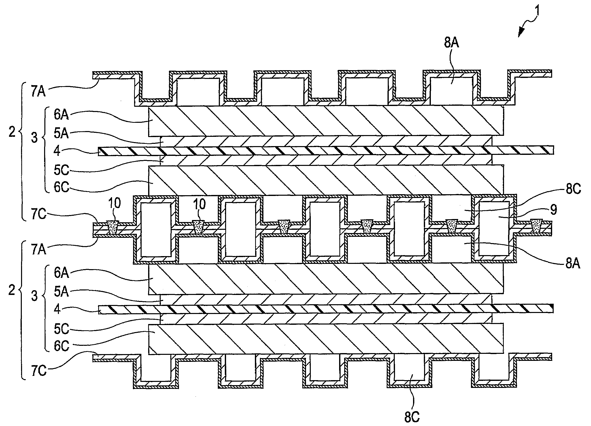
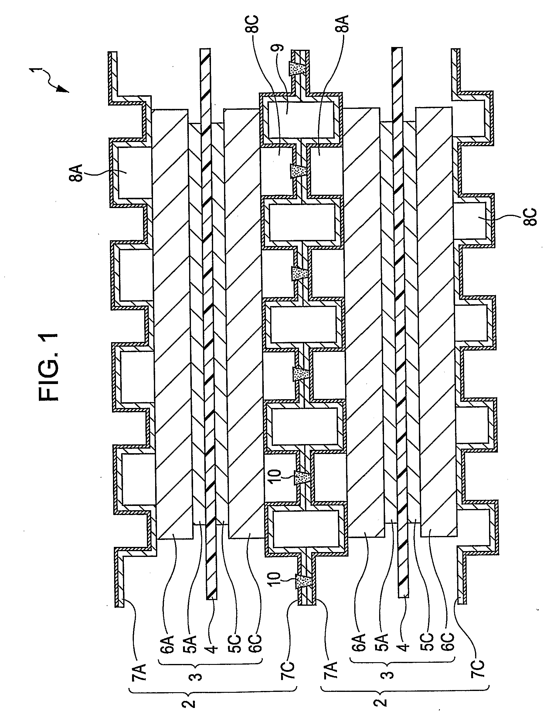
[0076]In Example 1, as shown in FIG. 5, linear welded portions 11 and dot welded portions 12 are provided on a first separator 7A and a second separator 7C in any arrangement in accordance with the dimensions of projecting portions 21 and 22, warping of the separators 7A and 7C after press forming, and the like.

[0077]When flow paths 8A, 8C, and 9 formed by the first separator 7A and the second separator 7C linearly extend, projecting portions 21 are in contact with each other without any clearance. On the other hand, when the flow paths 8A, 8C, and 9 have a serpentine shape, a clearance may be partly formed between the projecting portions 21. Accordingly, the linear welded portions 11 and dot welded portions 12 are appropriately arranged in combinations in accordance with a distribution state of contact portions of the first separator 7A and the second separator 7C.

[0078]When the ratio of a welded area (joined area) corresponding to the welded portion 10 to the contact area of the f...
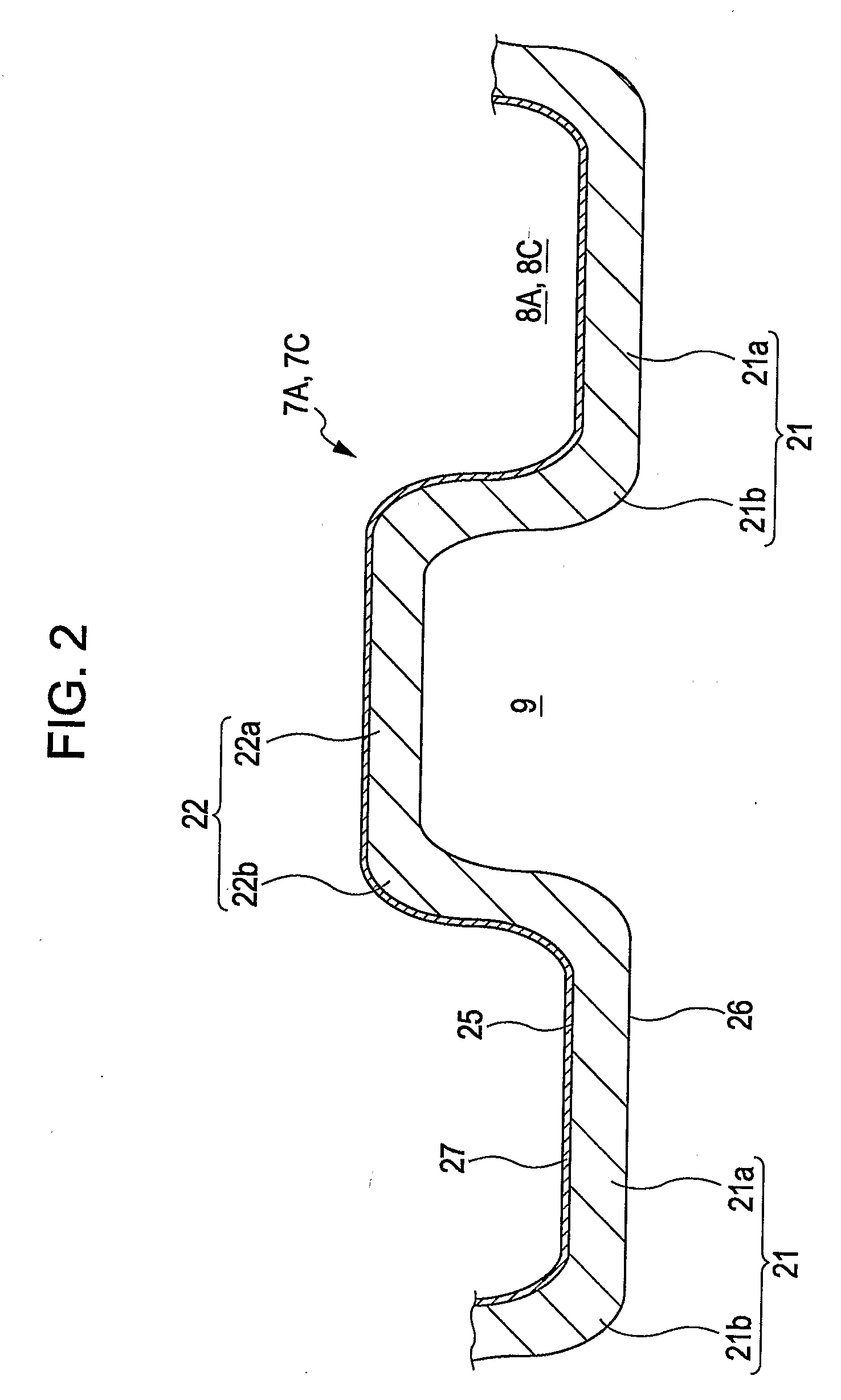
example 2

[0084]In Example 2, oxide films on the back surface 26 of the first separator 7A and the back surface 26 of the second separator 7C are removed and the back surfaces 26 thereof are then welded.

[0085]In this example, to remove the oxide film, base materials of the first separator 7A and the second separator 7C are immersed in a sulfuric acid-acidic solution, and a predetermined electrical potential is applied to the base materials.

[0086]FIG. 10 shows experimental results of measured penetration resistances of the first separator 7A and the second separator 7C in the case where the surface pressure between the first separator 7A and the second separator 7C was varied. In FIG. 10, characteristic A represents a result in the case where the welding was performed without removing the oxide films on the back surfaces 26, characteristic B represents a result in the case where the oxide films on the back surfaces 26 were removed with an acid and the welding was then performed, and characteri...

example 3

[0090]In Example 3, oxide films on the back surface 26 of the first separator 7A and the back surface 26 of the second separator 7C are removed by machining, i.e., grinding and the back surfaces 26 thereof are then welded.

[0091]The surface roughness of the back surface 26 of the first separator 7A and the back surface 26 of the second separator 7C is controlled to a predetermined surface roughness X-2 (see FIG. 12) at portions surrounded by the temperature-control medium flow path 9 so as to increase conductive properties. On the other hand, at portions facing gaskets (not shown), the surface roughness is controlled to a value smaller than the surface roughness X-2 so as to improve the sealing property.

[0092]FIG. 12 shows experimental results of measured penetration resistances of the first separator 7A and the second separator 7C, which were made of a metal X or a metal Y, in the case where the surface roughness of the back surface 26 of the first separator 7A and the back surface ...


PUM

PropertyMeasurementUnit
Fractionaaaaaaaaaa
Temperatureaaaaaaaaaa
Electrical resistanceaaaaaaaaaa

Abstract

A cell of a fuel cell includes a membrane electrode assembly, and metal first and second separators which sandwich the membrane electrode assembly to form gas flow paths disposed on each side of the membrane electrode assembly. A back surface of the first separator and a back surface of the second separator, the first separator and the second separator being included in adjacent cells, are in contact with each other, thereby forming a temperature-control medium flow path between the first separator and the second separator. In the first separator and the second separator, corrosion-resistant coating layers are provided only on reaction-side surfaces of the first separator and the second separator, the reaction-side surfaces facing the membrane electrode assembly, and portions where the back surface of the first separator is in contact with the back surface of the second separator are joined by welded portions.

Description

CROSS-REFERENCE TO RELATED APPLICATIONS[0001]This application claims priority to Japanese Patent Application No. 2006-136709, filed May 16, 2006, the disclosure of which is incorporated by reference herein in its entirety.BACKGROUND OF THE INVENTION[0002]1. Field of the Invention[0003]The present invention relates to a fuel cell stack and a method of producing the same. In particular, the present invention relates to a fuel cell stack that includes separators formed of a metal plate and a method of producing the same.[0004]2. Description of the Related Art[0005]Solid polymer fuel cells include a solid polymer electrolyte membrane having proton conductivity. In such solid polymer fuel cells, a fuel gas is supplied to an anode, which is one of a pair of electrodes provided so as to sandwich the electrolyte membrane, and an oxidizer gas is supplied to a cathode, which is another electrode. Solid polymer fuel cells generate electric power utilizing electrochemical reactions caused on th...

Claims


Application Information

Patent Timeline
IPC IPC(8): H01M8/04B23K37/00
CPCB23K26/246Y02T90/32H01M8/0206H01M8/021H01M8/0228H01M8/0254H01M8/0256H01M8/0258H01M8/0267H01M8/0297H01M8/04029H01M8/1004H01M2008/1095H01M2250/20Y02E60/521B23K26/3293B23K26/244B23K2101/34B23K2103/08Y02E60/50Y02P70/50Y02T90/40H01M8/241H01M8/2404H01M8/2457H01M8/2483
Inventor MIYAZAWA, ATSUSHIYAGINUMA, MOTOKIOBIKA, MOTOHARUTAKATA, KOSHIKINO, NOBUOFUKUYAMA, YOSUKE
Owner NISSAN MOTOR CO LTD
Why Eureka
Try Eureka