Optical transport system and resource optimization method

a technology of optical transport system and optimization method, which is applied in the field of optical transport system and resource optimization method, can solve the problems of difficult to expand single carrier transport in a band of one optical channel as before to achieve a larger capacity, and achieve the effect of eliminating fragmentation and enhancing resource utilization efficiency

Active Publication Date: 2017-11-09
NIPPON TELEGRAPH & TELEPHONE CORP
View PDF1 Cites 12 Cited by
  • Summary
  • Abstract
  • Description
  • Claims
  • Application Information

AI Technical Summary

Benefits of technology

[0018]According to the present invention, it is possible to enhance the utilization efficiency of resources by eliminating fragmentation that occurs in the allocation of time slots of a transport frame and by stopping power supply to a subcarrier transmission unit and a subcarrier reception unit that do not perform transmission and reception of client signals.

Problems solved by technology

However, because of an operational speed of an electronic circuit used for a transceiver of an optical signal, it is difficult to enlarge single carrier transport in a band of one optical channel as before to achieve a larger capacity.

Method used


Image

  • Optical transport system and resource optimization method
  • Optical transport system and resource optimization method
  • Optical transport system and resource optimization method

Examples


first embodiment

[0086]FIG. 5 is a block diagram showing a configuration of an optical transport system in a first embodiment of the present invention. As shown in the figure, the optical transport system in the first embodiment includes an optical transmitter 30, an optical receiver 40, and a transport path 50 (optical fiber). Further, FIG. 5 shows a frame structure used in the optical transmitter 30 and the optical receiver 40.

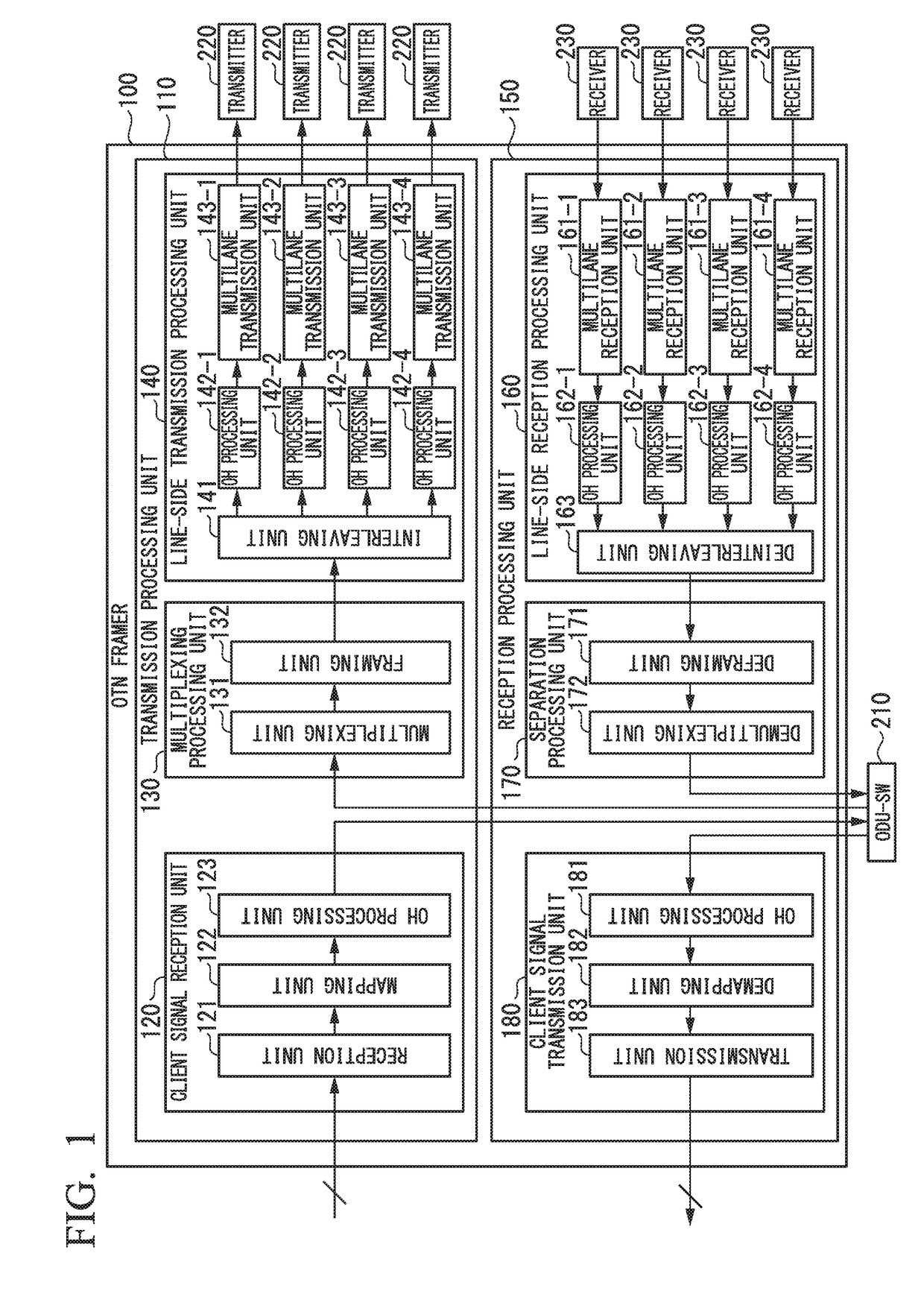
[0087]The optical transmitter 30 includes a plurality of client accommodation units 31, a time-multiplexing processing unit 32, a transport frame generation unit 33, i subcarrier transmission units 34-1 to 34-i, a time slot (TS) control unit 35, and a power source control unit 36. The client accommodation units 31 correspond to the client signal reception unit 120 in FIG. 1. The time-multiplexing processing unit 32 corresponds to the ODU-SW 210 and the multiplexing unit 131 in FIG. 1. The transport frame generation unit 33 corresponds to the framing unit 132 and the line-sid...

second embodiment

[0162]In the optical transport system in the first embodiment, when changing the allocation to time slots, signal cut-off occurs in the optical receiver 40 due to a guard time during which the same MSI is received a predetermined number of times and then use of a new MSI is started, a round-trip time of a transport multi-frame, or the like (FIG. 11). In an optical transport system in the second embodiment, an operation of preventing signal cut-off when changing the allocation of electric path signals to time slots is performed. In the optical receiver 40 in the second embodiment, setting of the guard time when switching a time slot utilization situation table is temporarily released, and the MSI is changed without receiving the same MSI a predetermined number of times.

[0163]FIG. 20 is a diagram showing an operation example of the optical transmitter 30 and the optical receiver 40 in the second embodiment. In FIG. 20, a lateral axis represents time. The optical receiver 40 receives a...

third embodiment

[0167]In the optical transport system in the first and second embodiments, switching information is transported using an overhead of a transport frame which serves as a main signal. In an optical transport system in accordance with a third embodiment, switching information is transported using a supervisory channel which is a signal having a wavelength that is different from that of the main signal, or using another communication path. FIG. 21 is a block diagram showing a configuration of the optical transport system in the third embodiment. As shown in the figure, the optical transport system in the third embodiment includes an optical transmitter 30A, an optical receiver 40A, and a transport path 50.

[0168]The optical transmitter 30A includes a plurality of client accommodation units 31, a time-multiplexing processing unit 32, a transport frame generation unit 33, i subcarrier transmission units 34-1 to 34-i, a TS (time slot) control unit 35, a power source control unit 36, and a c...


PUM


Abstract

In the optical transport system a transport frame generator divides a transport frame accommodating plural client signals into plural transmission signals. Subcarrier transmission units convert the signals into optical signals using different optical carriers and transmit the converted optical signals. Subcarrier reception units receive the transmitted optical signals and convert the optical signals into reception signals. A transport frame termination unit combines the reception signals to restore the transport frame. A time-demultiplexing processor time-demultiplexes the restored transport frame to be separated into the client signals. A time slot control unit determines a new time slot allocation when time-multiplexing the client signals in the transport frame and stops supply of electric power to a subcarrier transmission unit and a subcarrier reception unit that transmit and receive an optical signal to which the client signals are not allocated.

Description

TECHNICAL FIELD[0001]The present invention relates to an optical transport system and a resource optimization method.[0002]Priority is claimed on Japanese Patent Application No. 2014-241495, filed on Nov. 28, 2014, the content of which is incorporated herein by reference.BACKGROUND ART[0003]In an optical transport network (OTN), which is a large-capacity wide area photonic network, various client signals in a synchronous digital hierarchy (SDH), the Ethernet (registered trademark), and the like are accommodated and transferred. In recent years, increase in traffic of client signals is remarkable, and accordingly, standardization of the OTN has been advanced so as to cope with increase in speed (e.g., see Non-Patent Document 1). Currently, an OTUCn (Cn represents 100G×n), which is an OTN technique over 100G (B100G, in which G represents gigabits per second), is being studied (e.g., see Non-Patent Document 2). In the OTUCn, a transport capacity of one optical channel is broader than t...

Claims


Application Information

Patent Timeline
Patent Type & Authority Applications(United States)
IPC IPC(8): H04J3/06H04J14/02H04J3/16H04J14/08
CPCH04J3/0652H04J3/0623H04J3/1652H04J14/08H04J14/02H04J14/00H04J3/07H04J2203/006
Inventor YAMADA, YOSHIAKISHINTAKU, KENGOOHARA, TAKUYAKITAMURA, KEIKOTANIGAWA, TAKASHIHAMANO, TAKAFUMIARAI, KAORUYOKOTA, MASAHIROMAEDA, HIDEKI
Owner NIPPON TELEGRAPH & TELEPHONE CORP
Why Eureka
Try Eureka