Supercharge Your Innovation With Domain-Expert AI Agents!

Multiple tunable central cathodes on a paddle for increased medial-lateral and rostral-caudal flexibility via current steering

a technology of tunable central cathodes and current steering, which is applied in the field of tissue stimulation systems, can solve the problems of difficult to target all pain areas, difficult to achieve effective and ineffective pain therapy, and difficult to target areas (e.g., the lower back) particularly difficult to achiev

Active Publication Date: 2017-11-16
BOSTON SCI NEUROMODULATION CORP
View PDF2 Cites 0 Cited by
  • Summary
  • Abstract
  • Description
  • Claims
  • Application Information

AI Technical Summary

Benefits of technology

Enhances the precision and effectiveness of spinal cord stimulation by allowing for adjustable electrode spacing and current distribution, improving pain relief and minimizing unwanted stimulation, thus providing more efficient and comfortable treatment.

Problems solved by technology

Thus, correct lead placement can mean the difference between effective and ineffective pain therapy.
Even after successful placement of the leads in the operating room (with corresponding test stimulation), the SCS system typically requires electrical fine-tuning post-operatively, and often it is difficult to target all pain areas, with some areas (e.g., the lower back) being particularly difficult to target.
In particular, lead migration may relocate the paresthesia away from the pain site, resulting in the target neural tissue no longer being appropriately stimulated and the patient no longer realizing the full intended therapeutic benefit.
While change in the relative anode strengths will yield some tunability with a multiple source system, the electrical field is “tethered” to the single cathode, and so has limited flexibility in medial-lateral tuning.
However, because the physical spacing between the anodes and cathode is fixed, and prior art SCS systems do not have the capability of electrically adjusting the spacing between the flanking anodes and the single cathode, variations in the dCSF cannot be suitably accounted for in prior art SCS systems.
In addition, in a prior art medial-lateral arrangement, the electrodes are uniformly spaced and rostral-caudally aligned with each, which may not be the optimum arrangement.

Method used


Image

  • Multiple tunable central cathodes on a paddle for increased medial-lateral and rostral-caudal flexibility via current steering
  • Multiple tunable central cathodes on a paddle for increased medial-lateral and rostral-caudal flexibility via current steering
  • Multiple tunable central cathodes on a paddle for increased medial-lateral and rostral-caudal flexibility via current steering

Examples


Embodiment Construction

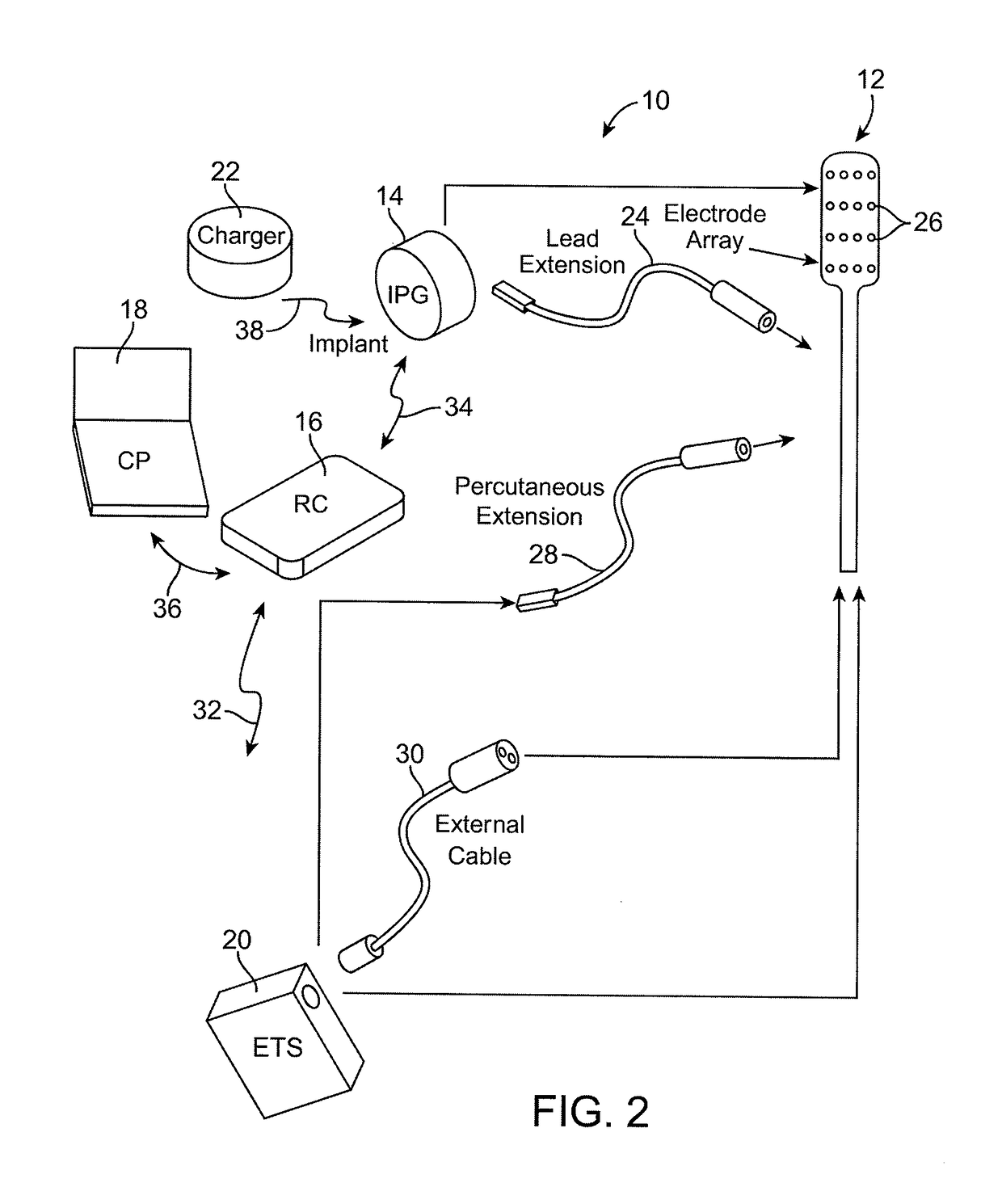
[0063]Turning first to FIG. 2, an exemplary spinal cord stimulation (SCS) system 10 generally comprises an implantable stimulation lead 12, an implantable pulse generator (IPG) 14 (or alternatively RF receiver-stimulator), an external remote control RC 16, a Clinician's Programmer (CP) 18, an External Trial Stimulator (ETS) 20, and an external charger 22.

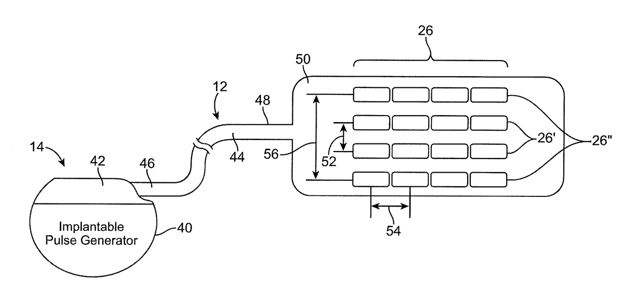
[0064]The IPG 14 is physically connected via a lead extension 24 to the stimulation lead 12, which carries a plurality of electrodes 26 arranged in an array. As will be described in further detail below, the IPG 14 includes pulse generation circuitry that delivers electrical stimulation energy in the form of a pulsed electrical waveform (i.e., a temporal series of electrical pulses) to the electrode array 26 in accordance with a set of stimulation parameters.

[0065]The ETS 20, which has similar pulse generation circuitry as the IPG 14, also provides electrical stimulation energy to the electrode array 26 in accordance with a set of s...


PUM


Abstract

A neurostimulation paddle lead, method of neurostimulation, and neurostimulation system are provided. The neurostimulation paddle lead carries a plurality of electrodes comprising at least four columns of electrodes having a spacing between two inner electrode columns less than a spacing between the inner electrode columns and adjacent outer electrode columns. The inner electrode columns may also be longitudinally offset from the outer electrode columns. The methods and neurostimulation systems steer current between the electrodes to modify a medial-lateral electrical field created adjacent spinal cord tissue.

Description

CLAIM OF PRIORITY[0001]This application is a continuation of U.S. application Ser. No. 12 / 204,114, filed Sep. 4, 2008, which is hereby incorporated by reference in its entirety.RELATED APPLICATIONS[0002]This application is filed concurrently with U.S. patent application Ser. No. 12 / 204,094, now U.S. Pat. No. 7,987,000, U.S. patent application Ser. No. 12 / 204,136, now U.S. Pat. No. 8,437,857, U.S. patent application Ser. No. 12 / 204,154, now U.S. Pat. No. 8,442,655 and U.S. patent application Ser. No. 12 / 204,170, now U.S. Pat. No. 9,504,818, the disclosures of which are expressly incorporated herein by reference.FIELD OF THE INVENTION[0003]The present invention relates to tissue stimulation systems, and more particularly, to systems and methods for electrically stimulating spinal cord tissue.BACKGROUND OF THE INVENTION[0004]Spinal cord stimulation (SCS) is a well-accepted clinical method for reducing pain in certain populations of patients. During SCS, the spinal cord, spinal nerve ro...

Claims


Application Information

Patent Timeline
Patent Type & Authority Applications(United States)
IPC IPC(8): A61N1/36A61N1/05
CPCA61N1/36185A61N1/0553A61N1/36017A61N1/36071
Inventor MOFFITT, MICHAEL A.LEE, DONGCHULBRADLEY, KERRYPETERSON, DAVID K.L.
Owner BOSTON SCI NEUROMODULATION CORP
Features
  • R&D
  • Intellectual Property
  • Life Sciences
  • Materials
  • Tech Scout
  • Unparalleled Data Quality
  • Higher Quality Content
  • 60% Fewer Hallucinations
Learn More