
Method And Apparatus For Motion Correction In CT Imaging

a motion correction and ct imaging technology, applied in the field of systems and methods, can solve problems such as distortion and blurring when images are reconstructed, false diagnosis, and images that are not interpretabl

Active Publication Date: 2017-11-30
WESTERN SYDNEY LOCAL HEALTH DISTRICT +2
View PDF0 Cites 11 Cited by
  • Summary
  • Abstract
  • Description
  • Claims
  • Application Information

AI Technical Summary

Benefits of technology

The patent describes a method for improving the accuracy of estimating the position of an object by using a helical CT image. The method involves measuring the image and comparing it to a predicted image produced by forward projection from a current pose estimate. The process is performed by iterating across multiple resolutions of the image, with increasing fidelity. The result is a more accurate estimate of the object's position.

Problems solved by technology

One of the major sources of image artifacts in computed tomography (CT) is patient motion, which creates inconsistencies between acquired projections, leading to distortion and blurring when images are reconstructed.
These motion artifacts may lead to false diagnosis, or in extreme cases, render images uninterpretable.
Head motion is a common problem in young patients who are often sedated or anesthetized to prevent motion.
Due to the relatively high radiation dose associated with CT scanning, it is undesirable to repeat the scan if motion occurs, particularly in children who have a much higher estimated lifetime risk of radiation-induced cancer than adults.
In adults, head motion is a problem for patients suffering from claustrophobia or a mental or behavioral incapacity, and in patients with head trauma.
A slight movement of the patient will lead to a reduction of spatial resolution in CT imaging, in severe cases resulting in corrupted images unsuitable for diagnosis or further processing.
To reduce the likelihood of motion artifacts, CT manufacturers have made scanners faster by increasing the number of detector rows and the rate of rotation of the x-ray source and detector, which is not a complete solution.
Motion correction is arguably simpler in CBCT since the entire object will normally be in the field of view at all times. In contrast, in helical CT, the object is always truncated in axial direction, which complicates the application of analytical motion correction algorithms.
Even with these techniques, errors are still visible in the resulting images.
The possible reason is that there still is some residual unrecorded motion in each pose, caused by small errors in the pose measurements.
This will result in ‘jagged’ artifacts which are most visible at the edge of the phantom.

Method used


Image

  • Method And Apparatus For Motion Correction In CT Imaging
  • Method And Apparatus For Motion Correction In CT Imaging
  • Method And Apparatus For Motion Correction In CT Imaging

Examples


Embodiment Construction

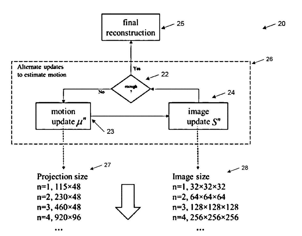
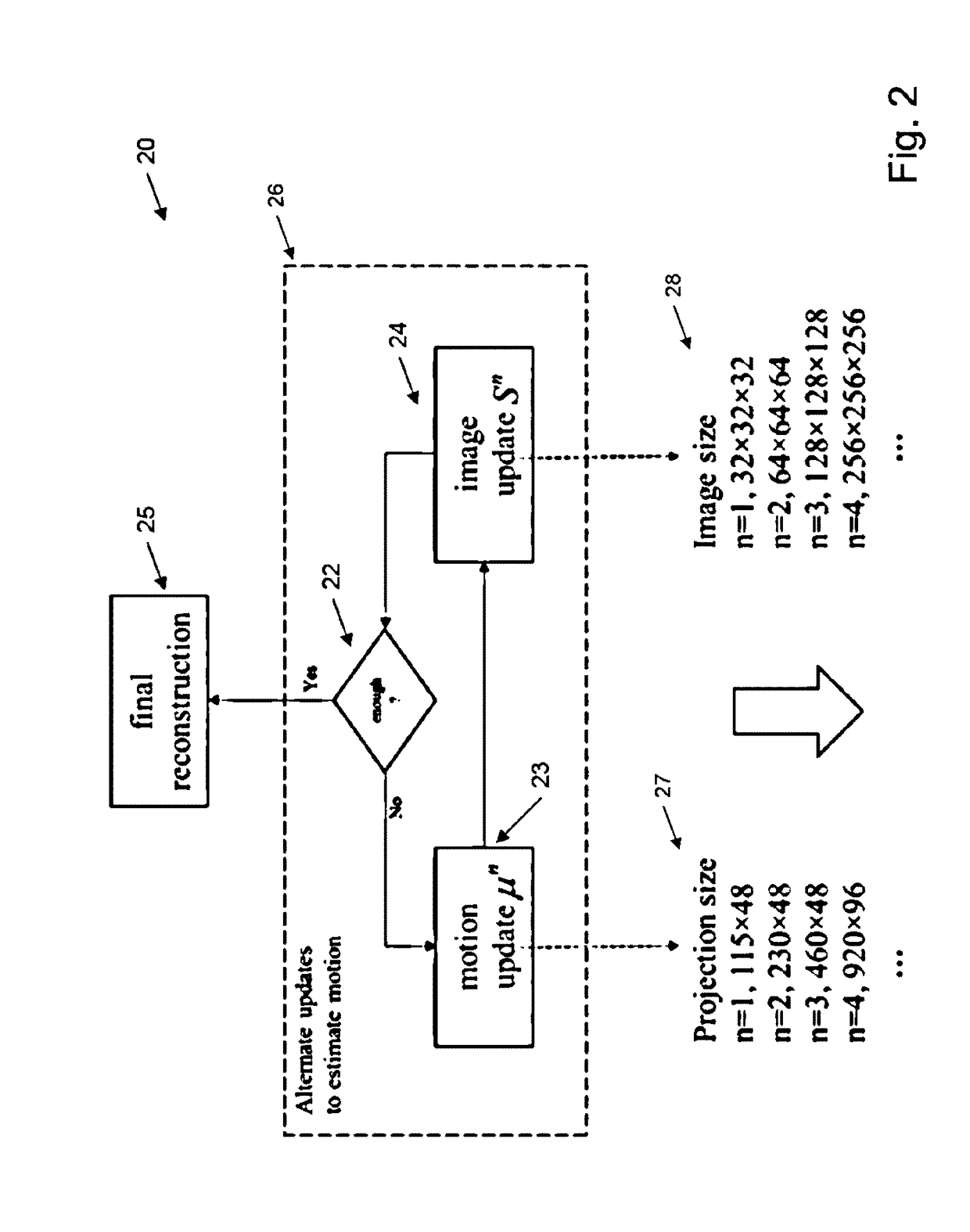
[0021]The preferred embodiments provide a data-driven method to iteratively correct for motion errors together with the reconstruction of helical CT imagery. In every iteration, an estimate of the motion is undertaken, view-by-view, which then can be used to update a system matrix which is used during reconstruction. A multi-resolution scheme was used to speed up the convergence of the joint estimation of the motion and reconstruction. The quality of the reconstructed images can be improved substantially after the correction.

[0022]The approach was found to reduce or eliminate the motion artifacts in helical-CT reconstruction. The correction method was found to only need the measured raw helical scan data, hence it is called a ‘data-driven’ approach.

[0023]The Method

[0024]Coordinate Systems:

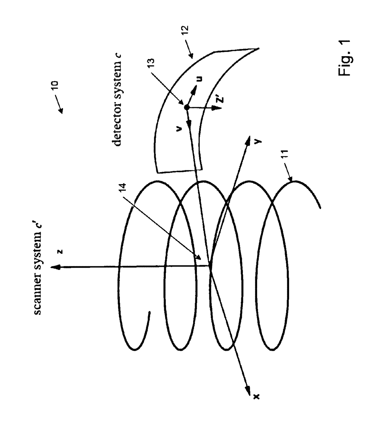
[0025]Turning initially to FIG. 1, there is shown the operational aspects 10 of a helical CT scan and associated coordinate systems. A clinical helical CT system usually has a curved detector 12. I...


PUM


Abstract

A method for the reduction of motion artifacts in a helical CT reconstruction, the method including the steps of: (a) reconstructing from the raw CT data an initial estimate of the 3D attenuation distribution of the object of interest; (b) estimating a pose parameter set of the object for each projection angle; (c) undertaking a motion corrected reconstruction from the measured projections, accounting for the pose changes estimated in (b); (d) iterating steps (b)-(c) until some convergence criterion is met; and (e) making a final reconstruction of diagnostic quality using the pose estimates obtained in the previous steps.

Description

FIELD OF THE INVENTION[0001]The present invention provides for systems and methods for the automated correction of motion artefacts in CT images, and, in particular, helical CT images.BACKGROUND OF THE INVENTION[0002]Any discussion of the background art throughout the specification should in no way be considered as an admission that such art is widely known or forms part of common general knowledge in the field.[0003]One of the major sources of image artifacts in computed tomography (CT) is patient motion, which creates inconsistencies between acquired projections, leading to distortion and blurring when images are reconstructed. These motion artifacts may lead to false diagnosis, or in extreme cases, render images uninterpretable. Head motion is a common problem in young patients who are often sedated or anesthetized to prevent motion. According to the latest available data, over 70 million CT scans are performed annually in the USA alone, of which approximately 10% are performed i...

Claims


Application Information

Patent Timeline
Patent Type & Authority Applications(United States)
IPC IPC(8): A61B5/00G06F3/0484
CPCG06F3/04847A61B5/721A61B5/7207A61B6/027A61B6/032A61B6/501A61B6/5264G06T11/003G06T2207/10081G06T2211/40G06T7/246G06T7/74G06T11/008G06T2211/424
Inventor FULTON, ROGERNUYTS, JOHANSUN, TAOKIM, JUNG-HA
Owner WESTERN SYDNEY LOCAL HEALTH DISTRICT
Learn More