

Stabilizer
a technology of stabilizer and stabilizer, which is applied in the direction of shock absorbers, heat treatment devices, furnaces, etc., can solve the problems of relatively high production cost and achieve the effect of improving fatigue durability
Active Publication Date: 2017-12-07
NHK SPRING CO LTD
View PDF0 Cites 3 Cited by
- Summary
- Abstract
- Description
- Claims
- Application Information
AI Technical Summary
Benefits of technology
The present invention provides a low-cost stabilizer that has improved fatigue durability. This is achieved by giving the stabilizer an outer layer with a deeply distributed compressive residual stress.
Problems solved by technology
A hollow stabilizer has characteristics of being suited to reduce the weight of a vehicle, but requiring relatively high production cost because an electro-welded steel pipe, a drawn steel pipe, or the like is used as the raw material.
Method used
View moreImage
Smart ImageViewing Examples

Examples
example 1-1
[0139]Using the test material 1 shown in Table 1 as the material, the vehicle stabilizer according to Example 1-1 was produced by carrying out the forming step S30 by cold bending process and the quenching step S40 by water quenching without performing tempering. Note that the vehicle stabilizer had a diameter of 23 mm.
example 1-2
[0140]The vehicle stabilizer according to Example 1-2 was produced in the same manner as in Example 1-1, except that the material was changed to the test material 4 shown in Table 1.
example 1-3
[0141]The vehicle stabilizer according to Example 1-3 was produced in the same manner as in Example 1-1, except that the forming step S30 was changed to hot bending process.
Login to View More PUM
| Property | Measurement | Unit |
|---|---|---|
| diameter | aaaaa | aaaaa |
| depth | aaaaa | aaaaa |
| Rockwell hardness | aaaaa | aaaaa |
Abstract
A stabilizer formed by using a metal bar having a solid structure and configured to reduce a displacement between right and left wheels, including a torsion part extending in a vehicle width direction, being capable of a torsional deformation, and having a diameter of 10 to 32 mm, is provided. The stabilizer has a chemical composition containing at least C: 0.15% by mass or more to 0.39% by mass or less, Mn, B, and Fe, and also has a metal structure 90% or more of which is a martensite structure.
Description
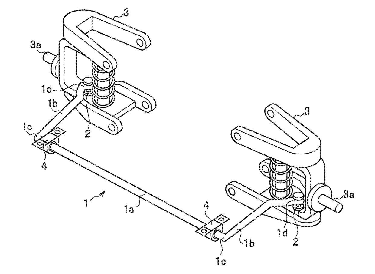
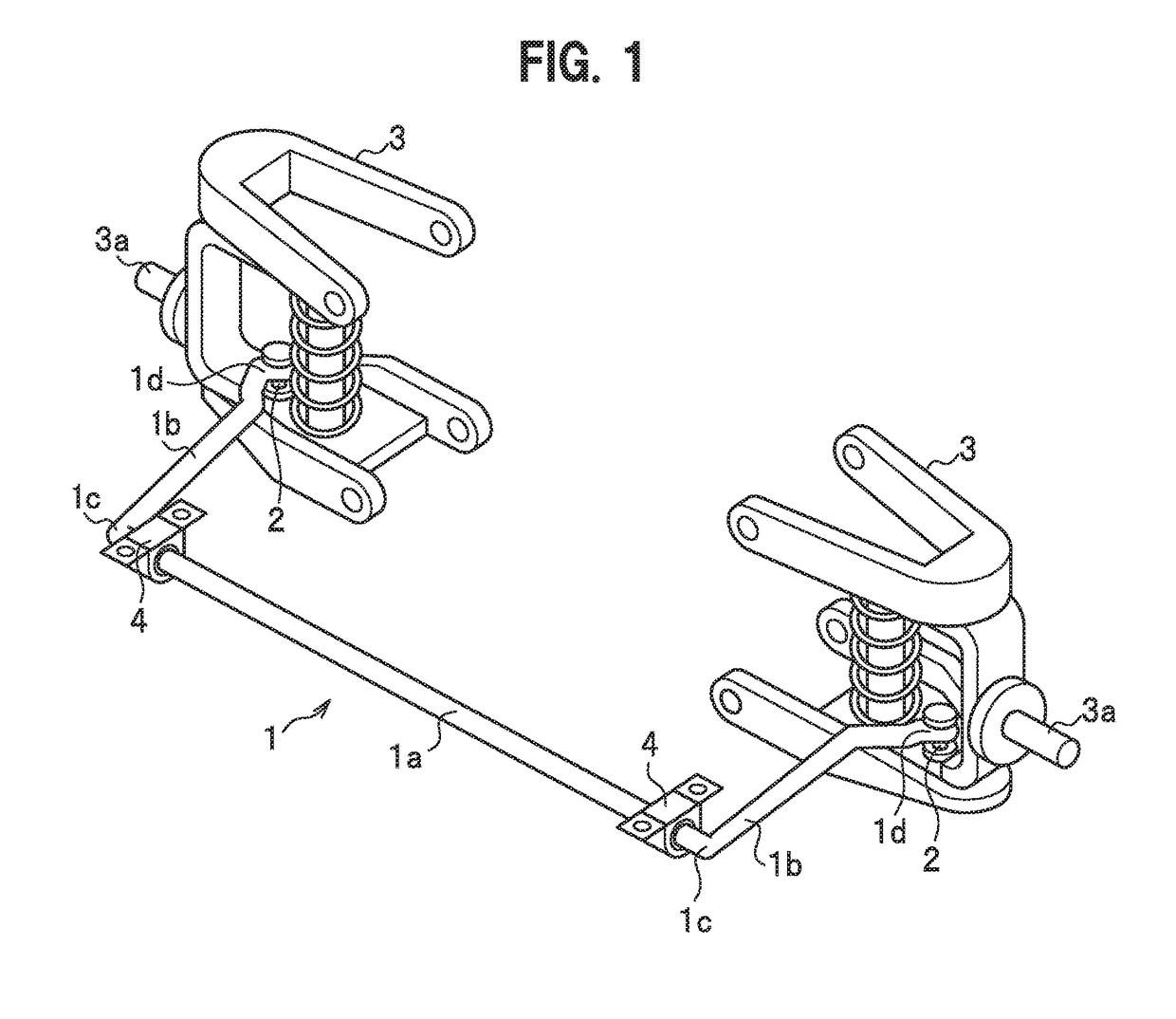
TECHNICAL FIELD[0001]The present invention relates to a stabilizer having a solid structure.BACKGROUND ART[0002]A vehicle such as an automobile includes a vehicle stabilizer (stabilizer bar or anti-roll bar) configured to reduce rolling of the vehicle body due to vertical movements of the wheels. Commonly, a vehicle stabilizer is a substantially U-shaped bar including a torsion part extending in a vehicle width direction, and a pair of right and left arm parts bent in a vehicle front-rear direction. In a vehicle, a vehicle stabilizer is suspended and supported between the right and left suspension devices with tip ends of the arm parts respectively connected to suspension devices of wheels, and the torsion part inserted in bushes fixed to the vehicle body.[0003]During driving, when a vehicle turns at a corner or runs over a bump on the road surface, a stroke difference between the right and left suspension devices occurs depending on a vertical positional difference between the righ...
Claims
Login to View More Application Information
Patent Timeline
 Patent Type & AuthorityApplications(United States)
IPC IPC(8): C21D9/00B21D47/00C22C38/42C22C38/04C22C38/02C22C38/00C22C38/44B21D53/88C21D8/06C21D7/06C21D6/00C21D1/60B60G21/055B24C1/10C22C38/54
CPCC21D9/0068C21D2211/008B21D47/00B21D53/88B60G21/055C21D8/065C21D7/06C21D6/004C21D6/005C21D6/008C21D1/60C22C38/54C22C38/44C22C38/42C22C38/04C22C38/02C22C38/002B60G2206/81035B24C1/10C22C38/60F16F1/14C21D9/0075B60G2206/427B60G2206/724B60G2206/8402B60G2206/8403C22C38/58C22C38/38F16F1/021F16F2224/0208F16F2226/00B24C1/08C21D8/06C21D9/00C22C38/00C21D9/02
InventorKUWATSUKA, SHINICHIROOKUDAIRA, YURIKATANGE, AKIRAOKADA, HIDEKITAKAHASHI, KEN
OwnerNHK SPRING CO LTD