Steel material and expandable oil country tubular goods

a technology of expandable oil country tubular goods and steel materials, which is applied in the direction of manufacturing tools, furnaces, heat treatment equipment, etc., can solve the problems of increasing drilling cost and construction period, and achieve excellent ssc resistance, high expandability, and uniform elongation.

Inactive Publication Date: 2017-12-07
NIPPON STEEL CORP
View PDF5 Cites 1 Cited by
  • Summary
  • Abstract
  • Description
  • Claims
  • Application Information

AI Technical Summary

Benefits of technology

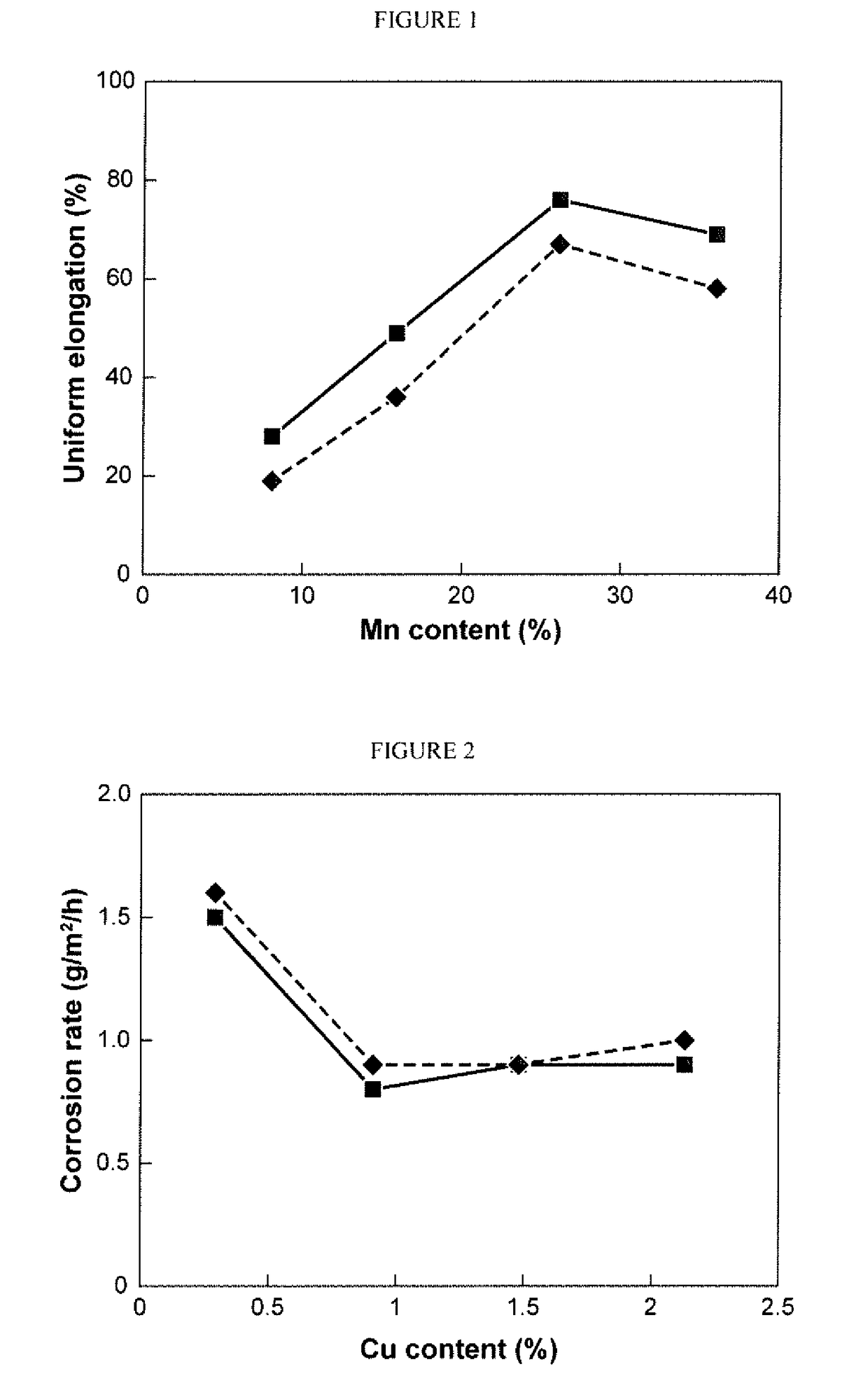
[0062]According to the present invention, a steel material having a high uniform elongation and thus a high expandability, and excellent SSC resistance after cold working can be obtained. Therefore, the steel material according to the present invention can be used suitably for expandable oil country tubular goods in wet hydrogen sulfide environments.

Problems solved by technology

Therefore, conventionally, in the case where it is necessary to perform drilling up to a large depth, a drilling area of the oil well in a stratum-near-surface portion becomes larger in an outside-diameter direction because of the increase in the number of times a casing is inserted, which increases drilling cost and construction period, and is thus economically disadvantageous.

Method used


Image

  • Steel material and expandable oil country tubular goods

Examples


example 1

[0143]Twenty-three kinds of steels of A to P and AA to AG having the chemical compositions given in Table 1 were melted in a 50 kg vacuum furnace to produce ingots. Each of the ingots was heated at 1180° C. for 3 h, and thereafter was forged and cut by electrical discharge cutting-off. Thereafter, the cut ingots were further soaked at 1150° C. for 1 h, and were hot-rolled into plate materials having a thickness of 20 mm. Subsequently, the plate materials were subjected to solid solution heat treatment at 1100° C. for 1 h to obtain test materials (test Nos. 1 to 23). Additionally, test materials produced in the same manner as test Nos. 1 to 23 are further cold-rolled at a working ratio of 10% to obtain strengthened test materials (test Nos. 24 to 46).

TABLE 1Chemical composition (in mass %, balance: Fe and impurities)SteelCSiMnAlPSCuNVCrMoA1.210.2926.120.0330.0120.0061.480.013———B1.190.3036.000.0360.0100.0061.510.012———C1.160.2725.950.0280.0140.0040.910.013———D1.210.2826.130.0310.0130...

example 2

[0156]Effects of aging heat treatment after solid solution treatment were investigated using steels K, L, O and AF which were prepared in EXAMPLE 1. The condition of solid solution heat treatment is same as EXAMPLE 1. Additionally the aging heat treatment is performed under the condition of 800° C. and 1 hour. The method for evaluation test was same as EXAMPLE 1.

[0157]Metal micro-structures of the aging heat treated test materials before and after the cold working at the working ratio of 25% were investigated by using the ferrite meter as is the case with EXAMPLE 1. For all of the test materials before the cold working, the phases having BCC structures could not be detected and the metal micro-structures were austenite single phases. Therefore, the volume amounts of the phases having BCC structures for the test materials only after the cold working are shown as a BCC ratio by volume % in tables. The results are given in Table 4.

TABLE 4After aging heat treatmentAfter simulated expans...


PUM

PropertyMeasurementUnit
uniform elongationaaaaaaaaaa
yield strengthaaaaaaaaaa
elongationaaaaaaaaaa

Abstract

There is provided a steel material having a chemical composition consisting, by mass percent, of C: 0.6-1.8%, Si: 0.05-1.00%, Mn: >25.0-45.0%, Al: 0.003-0.06%, P: ≦0.03%, S: ≦0.03%, Cu: 0.5-3.0%, N: ≦0.10%, V: 0-2.0%, Cr: 0-3.0%, Mo: 0-3.0%, Ni: 0-1.5%, Nb: 0-0.5%, Ta: 0-0.5%, Ti: 0-0.5%, Zr: 0-0.5%, Ca: 0-0.005%, Mg: 0-0.005%, REM: 0-0.01%, B: 0-0.015%, the balance: Fe and impurities, and satisfying [0.6<C−0.18V<1.44], wherein a metal micro-structure is consisting of an austenite single phase, a yield strength is 241 MPa or higher, and a uniform elongation is 40% or higher.

Description

TECHNICAL FIELD[0001]The present invention relates to a steel material and expandable oil country tubular goods, and more particularly, to a steel material excellent in pipe expendability and sulfide stress cracking resistance, which is used in oil well and gas well environments and the like environments containing hydrogen sulfide (H2S) and expandable oil country tubular goods using the same.BACKGROUND ART[0002]In drilling of oil wells and gas wells (hereinafter, collectively referred to simply as “oil wells”), a general method employed is to insert and bury casings after a drill hole reaches a predetermined depth in order to prevent a well wall from collapsing. Furthermore, the operation of inserting casings having smaller outside diameter one by one is repeated while performing the drilling. Therefore, conventionally, in the case where it is necessary to perform drilling up to a large depth, a drilling area of the oil well in a stratum-near-surface portion becomes larger in an ou...

Claims


Application Information

Patent Timeline
Patent Type & Authority Applications(United States)
IPC IPC(8): C22C38/38C21D8/02C22C38/20C22C38/16C22C38/14C21D9/46C22C38/08C22C38/06C22C38/04C22C38/02C22C38/00C22C38/22C22C38/32C22C38/12
CPCC22C38/38C21D2211/001C22C38/22C22C38/20C22C38/16C22C38/14C22C38/12C22C38/08C22C38/06C22C38/04C22C38/02C22C38/002C22C38/005C22C38/001C21D9/46C21D8/0226C21D8/0263C21D8/0205C21D8/0236C22C38/32C21D8/02C22C38/58
Inventor KOBAYASHI, KENJITOMIO, YUSAKU
Owner NIPPON STEEL CORP
Why Eureka
Try Eureka