Corrosion resistant alloy weldments in carbon steel structures and pipelines to accommodate high axial plastic strains

a technology of corrosion resistance and alloy welds, which is applied in the direction of service pipe systems, manufacturing tools, and solventing apparatus, etc., can solve the problems of limited global plastic strain capacity of pipelines, which may be referred to as global strain capacity, and achieve the effect of simplifying the weld testing and qualification regimen

Active Publication Date: 2015-05-26
EXXONMOBIL UPSTREAM RES CO
View PDF110 Cites 0 Cited by
  • Summary
  • Abstract
  • Description
  • Claims
  • Application Information

AI Technical Summary

Benefits of technology

[0013]The present invention provides a technique for producing resilient weld joints between ferritic structural steel components whereby the weldment is beneficial to strain-based designs. Strain-based design refers to design of structural components that are capable of absorbing predicted global plastic strains while in service. The weld metals provided by this invention are superior to conventional ferritic welds for strain-based designs. They are capable of absorbing high strains, can permit the acceptance of larger weld flaws without repair, and can simplify the weld testing and qualification regimen of a typical construction project. The welds provided by this invention are unique to strain-based applications in that they are made using weld consumables that are nominally austenitic in microstructure. Corrosion resistant alloy (CRA) welding consumables are a name that is used in the current invention to refer to this group of welding consumables. This group includes, but is not limited to, nickel-based alloys, stainless steels, and duplex stainless steels, or similar. Examples of such consumables include, but are not limited to, American Welding Society (AWS) ENiCrMo-4, ENiCrMo-6, ENiCrMo-14, ENiMo-3, E310, E308, E316, E2209 and E2553, derivatives and alloys thereof.
[0014]In one or more of the embodiments of the invention, any of the typical API (American Petroleum Institute) Pipe Specification 5L pipe grades (such as X52 up to X80, or X100, or X120) can be welded with the CRA consumables. The resultant girth weld is capable of withstanding global plastic strains in excess of 0.5%, preferably in excess of 1%, more preferably in excess of 1.5%, or even more preferably in excess of 2%. For demanding applications, the CRA consumables can be applied to achieve global plastic strains in excess of 4% strain. The global plastic strain that a pipeline can sustain, which may be referred to as the global strain capacity, is limited by the properties of the girth welds and pipeline steel. For example, in the case of a pipeline comprising large diameter carbon-manganese steel pipes coupled by girth welds, typical global strain capacities may range from values less than yielding of about 0.3% strain to about 0.5% strain, and up to about 8% strain, or in some cases up to 10% strain, or up to about 15% or 20% strain, which represents a practical upper limit for global strain capacity of steel pipelines. The global strain capacity for the girth weld and the joined material may be determined from experimental data or estimated from experience. Further, the combination of ferritic structural steel components and the CRA welding consumables produces a weld that achieves the resilient strain properties by possessing a superior combination of mechanical properties. These properties include low yield strength to tensile strength ratio, high uniform elongation, and good toughness and tearing resistance. A combination of these properties enables these welds to achieve high plastic strains even though these welds can in some circumstances produce undermatched yield strengths compared to the base metal of up to 10%, or possibly 20%, or even in some cases as much as 30%. These welds are ideally suited for creating girth welds used in constructing large diameter oil and gas transmission pipelines when a strain-based design is desired.

Problems solved by technology

The global plastic strain that a pipeline can sustain, which may be referred to as the global strain capacity, is limited by the properties of the girth welds and pipeline steel.

Method used


Image

  • Corrosion resistant alloy weldments in carbon steel structures and pipelines to accommodate high axial plastic strains
  • Corrosion resistant alloy weldments in carbon steel structures and pipelines to accommodate high axial plastic strains
  • Corrosion resistant alloy weldments in carbon steel structures and pipelines to accommodate high axial plastic strains

Examples


Embodiment Construction

Introduction and Definitions

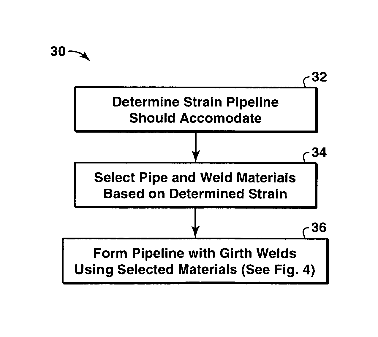
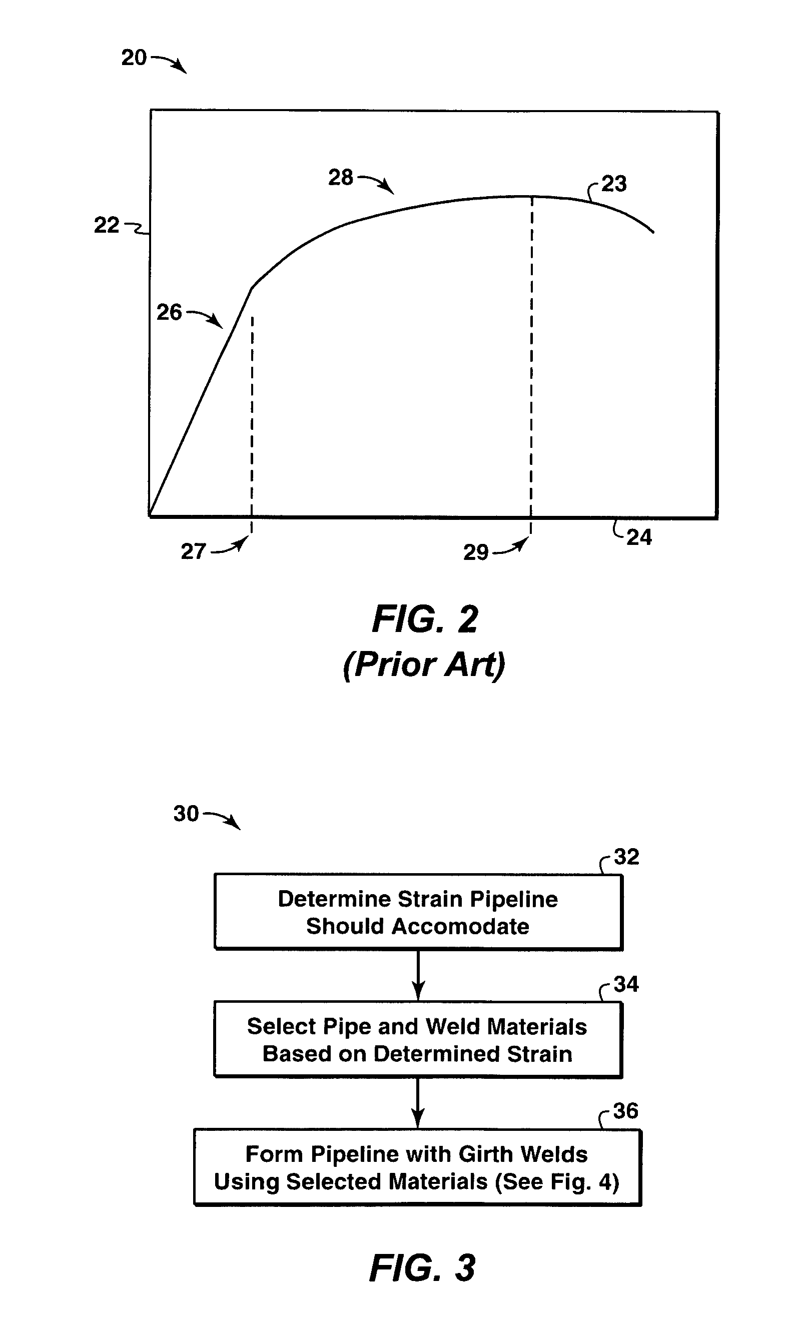
[0024]Embodiments of the present invention provide a method and apparatus that may be used to join two ferritic metals using austenitic weld materials.

[0025]Joining tubular sections of a pipeline made of a material exhibiting a primarily ferritic microstructure is a specific, but not limiting, example of an application in which techniques in accordance with embodiments of the present invention may be used to advantage. However, those skilled in the art will recognize that similar techniques may also be used in a variety of other applications, for example, where high axial loading and plastic strains are expected.

[0026]As used herein, the term strain-based design refers to the design of a structure such that the environmental and operational loads are quantified in terms of the applied strains and the limits on loads are expressed in terms of strain limits that allow a certain amount of plastic strain to occur.

[0027]As used herein, the term corrosion resis...


PUM

PropertyMeasurementUnit
widthaaaaaaaaaa
widthaaaaaaaaaa
sizeaaaaaaaaaa

Abstract

A method and apparatus for joining materials having primarily ferritic properties is described. The method includes joining the ferritic materials using a welding process and a weld material having a primarily austenitic microstructure. The resulting weldment enhances the properties of yield ratio, uniform elongation, toughness and tearing resistance thereby producing superior strain capacity. High strain capacity produces a structure that accommodates high axial loading. The weldment can also accommodate larger than conventional weld flaws while maintaining sufficient strength, tearing resistance, and fracture toughness under high axial loading.

Description

CROSS REFERENCE TO RELATED APPLICATIONS[0001]This application is the National Stage of International Application No. PCT / US2008 / 001409, filed 31 Jan. 2008, which claims the benefit of U. S. Provisional Application No. 60 / 903,765, filed 27 Feb. 2007.BACKGROUND OF THE INVENTION[0002]The present invention relates to methods for joining two pieces of metal. More specifically, in using austenitic weld materials to join two ferritic materials, which may be utilized in the production or transport of fluids, such as hydrocarbons, or other strain based applications.DESCRIPTION OF THE RELATED ART[0003]Typically, plain carbon and low alloy steel weld consumables produce welds that are dominated by ferritic microstructures. Common microstructural components in these ferritic weld metals include ferrite, pearlite, bainite, martensite or derivatives or mixtures of these components. These ferritic welds typically have limitations in toughness and tearing resistance, particularly at low temperature...

Claims


Application Information

Patent Timeline
Patent Type & Authority Patents(United States)
IPC IPC(8): F16L9/14B23K9/23B23K31/12C21D8/10
CPCB23K31/12B23K9/23C21D8/10B23K2203/04B23K2103/04B23K2103/05B23K2103/18Y10T137/402
Inventor BEESON, DANNY L.LEBLEU, JR., JAMES B.
Owner EXXONMOBIL UPSTREAM RES CO
Why Eureka
Try Eureka