Systems and methods for generating liquid water from air
Active Publication Date: 2017-12-14
ARIZONA STATE UNIVERSITY
View PDF0 Cites 24 Cited by
Summary
Abstract
Description
Claims
Application Information
AI Technical Summary
This helps you quickly interpret patents by identifying the three key elements:
Problems solved by technology
Method used
Benefits of technology
Benefits of technology
The present patent describes systems and methods for generating liquid water from air using a desiccant. The systems include a housing with an adsorption zone and a desorption zone, a desiccant that moves between the two zones, a first blower to adjust airflow, a circulator to adjust fluid flow, a thermal unit to provide heat to the process air, a condenser to produce liquid water, and a controller to optimize liquid water production based on ambient air conditions such as temperature, humidity, and solar insolation. The systems can adjust the rate of desiccant movement and the speed of the blower and circulator to optimize liquid water production. The patent also describes a method for controlling the system based on measurements of the ambient air conditions.
Problems solved by technology
Numerous devices and methods for obtaining potable water from atmospheric humidity have been considered; however, most concepts are less than attractive for various reasons, including: a need for external power, a high degree of complexity, a low liquid water production rate, a high inefficiency, impurities in produced water, a high system cost, and / or a need for a large tract of land.
The disadvantages of such systems may include a high degree of complexity, a large size, a low liquid water production rate, high inefficiencies, high electrical power requirements for operation, and / or the like.
Furthermore, many such systems require complex and energy-intensive components (e.g., compressors, components used in refrigeration cycles, and / or the like).
Some such systems that operate in different day and night modes may produce amounts of impure water, which may not meet potable water requirements for human consumption.
Method used
Image
Click on the blue label to locate the original text in one second.
Reading with bidirectional positioning of images and text.
Examples
first embodiment
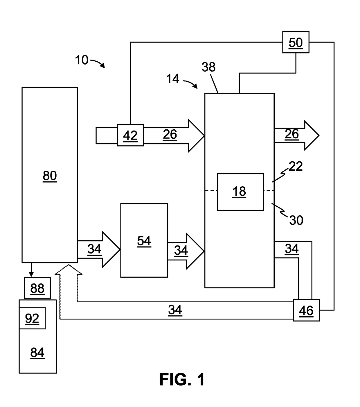
[0076]Referring now to the drawings, and more particularly to FIG. 1, shown therein and designated by the reference numeral 10 is the present systems for generating liquid water from air. In the embodiment shown, system 10 is configured to function responsive to diurnal variations. For example, as described in more detail below, system 10 is configured to control one or more operational parameters (e.g., control and / or controlled variables) based on one or more diurnal variations (e.g., variations in ambient air temperature, ambient air relative humidity, solar insolation, and / or the like).
embodiment 174
[0077]Throughout the following description, illustrative views of example components which may be suitable for use in some of the systems described below (e.g., 10, 98) are provided in FIGS. 17A-17C, which collectively depict an embodiment 174 of the present systems. The views of system 174, shown in FIGS. 17A-17C, are provided only by way of illustration, and not by way of limitation. In other words, FIGS. 17A-17C may be used to illustrate and / or provide additional description of certain components of systems 10 and / or 98, but shall not be used to limit systems 10 and / or 98.
[0078]In this embodiment, system 10 comprises a desiccant unit 14. In the depicted embodiment, desiccant unit 14 comprises a desiccant (e.g., sorption medium) 18, where the desiccant 18 (e.g., or a portion thereof) is selectively (e.g., and / or alternatively) movable between an adsorption zone 22, in which the desiccant is in fluid communication with a process air pathway (e.g., a process airflow path) 26 and a d...
embodiment 98
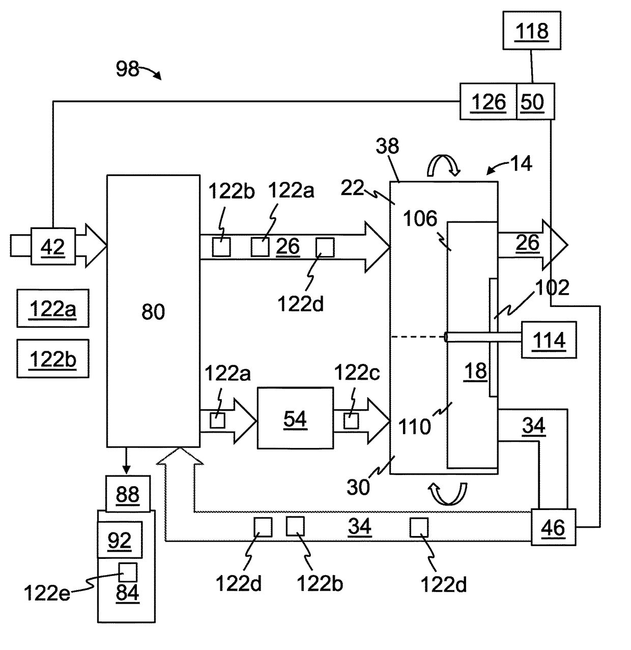
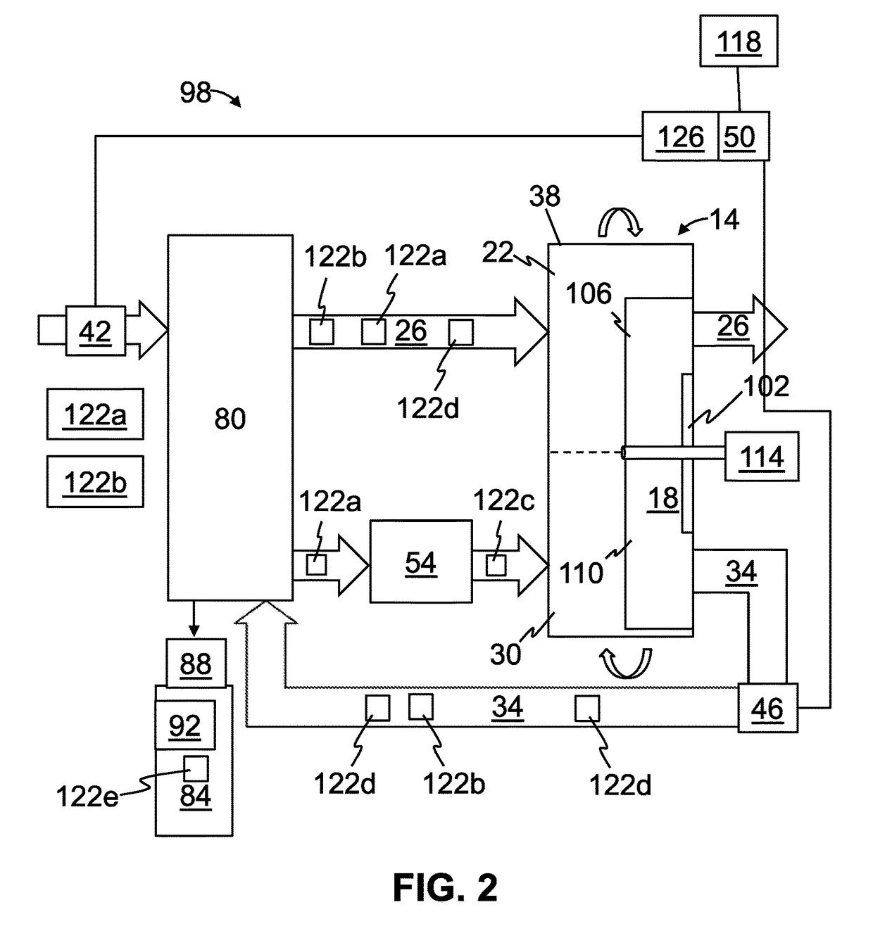
[0097]FIG. 2 is a diagram of an embodiment 98 of the present systems for generating liquid water from air. System 98 may be substantially similar to system 10, with the primary differences and / or additions described below. Otherwise, system 98 may comprise any and / or all features described with respect to system 10.
[0098]In system 98, as with system 10, desiccant 18 (or a first portion thereof) can be in fluid communication with process air in process air pathway 26 while the desiccant 14 (or a second portion thereof) is simultaneously in fluid communication with regeneration fluid in regeneration fluid pathway 34, and, thus, desiccant unit 14 operates in a continuous and non-batch manner. In this embodiment, sections of desiccant 18 are each exposed to air in process air pathway 26 and fluid in regeneration fluid pathway 34 in an alternating manner.
[0099]In the embodiment shown, system 98 comprises a rotatable disk 102 (e.g., with desiccant 18 disposed thereon). In this embodiment,...
PUM
Abstract
This disclosure includes systems and methods for extracting water vapor from atmospheric air and, more particularly, but not by way of limitation, systems and methods for optimizing liquid water production from air, in some instances, taking into account diurnal variations. The systems comprise an adsorption zone an a desorption zone, an actuator to move a desiccant between the adsorption zone and the desorption zone. The liquid water production is optimized based, at least in part, on measurements of one or more of: an ambient air temperature, ambient airrelative humidity, and a level of solar insolation.
Description
BACKGROUND[0001]This application claims the benefit of priority to U.S. Provisional Patent Application Ser. No. 62 / 082,335, filed Nov. 20, 2014, and U.S. Provisional Patent Application Ser. No. 62 / 145,995, filed Apr. 10, 2015, each of which are hereby incorporated by reference in their entirety.1. FIELD OF INVENTION[0002]The present invention is generally related to the extraction of water vapor from atmospheric air and more specifically, but not by way of limitation, to systems and methods for efficiently generating liquid water from air at an optimized liquid water production rate, in some instances, taking into account diurnal variations in ambient conditions.2. DESCRIPTION OF RELATED ART[0003]Numerous devices and methods for obtaining potable water from atmospheric humidity have been considered; however, most concepts are less than attractive for various reasons, including: a need for external power, a high degree of complexity, a low liquid water production rate, a high ineffic...
Claims
Application Information
Patent Timeline
Application Date:The date an application was filed.
Publication Date:The date a patent or application was officially published.
First Publication Date:The earliest publication date of a patent with the same application number.
Issue Date:Publication date of the patent grant document.
PCT Entry Date:The Entry date of PCT National Phase.
Estimated Expiry Date:The statutory expiry date of a patent right according to the Patent Law, and it is the longest term of protection that the patent right can achieve without the termination of the patent right due to other reasons(Term extension factor has been taken into account ).
Invalid Date:Actual expiry date is based on effective date or publication date of legal transaction data of invalid patent.

