LED structure with polarized light emission

a diode and led structure technology, applied in the field of led structure with polarized light emission, can solve the problems of difficult to make or have less than desired polarization, difficult to make large polarizer and diffuser layers, and difficult to make them over large areas, so as to reduce the cost of polarizing light, reduce the number of layers, and improve efficiency.

Active Publication Date: 2017-12-14
X DISPLAY CO TECH LTD
View PDF6 Cites 40 Cited by
  • Summary
  • Abstract
  • Description
  • Claims
  • Application Information

AI Technical Summary

Benefits of technology

[0012]Certain embodiments of the present invention provide a reduced number of layers, weight, thickness, and improved efficiency. By integrating many micro-transfer printed micro-LEDs on small substrates and providing a polarizer on each of the substrates, the cost to polarize light is reduced, uniformity is improved, and a thinner device with fewer layers and reduced weight is provided.

Problems solved by technology

Since wire-grid polarizers used in displays require very fine lithography, for example having wires with a pitch comparable to the wavelength of visible light, it is difficult to make them over large areas.
However, such structures are difficult to make or can have less than desired polarization.
Furthermore, for large displays it can be difficult to make the large polarizer and diffuser layers.

Method used


Image

  • LED structure with polarized light emission
  • LED structure with polarized light emission
  • LED structure with polarized light emission

Examples


Embodiment Construction

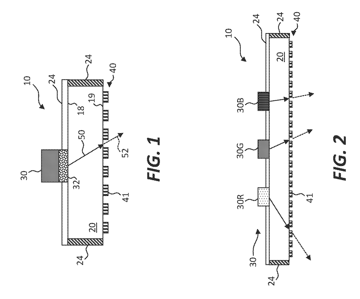
[0047]Referring to the cross sections of FIGS. 1 and 2, in some embodiments of the present invention a light-emitting diode (LED) structure 10 comprises an LED substrate 20 having a first side 18 and a second side 19 opposing the first side 18. One or more light-emitting diodes (LEDs) 30 are disposed on the first side 18 and arranged to emit light through the LED substrate 20 and through the opposing second side 19. A wire-grid polarizer 40 having an array of wires 41 is disposed on the second side 19 and arranged to linearly polarize light emitted from the one or more light-emitting diodes 30. In operation, the LED 30 is provided with suitable electrical power to cause the LED 30 to emit unpolarized light 50 through the LED substrate 20 and the opposing second side 19 to the wire-grid polarizer 40. The wire-grid polarizer 40 linearly polarizes the unpolarized light 50 emitted from the LED 30 to emit polarized light 52 from the LED structure 10.

[0048]The LEDs 30 can have a substrate...


PUM

PropertyMeasurementUnit
sizeaaaaaaaaaa
sizeaaaaaaaaaa
sizeaaaaaaaaaa

Abstract

A light-emitting diode (LED) structure includes an LED substrate having a first side and a second side opposing the first side. One or more light-emitting diodes are disposed on the first side and arranged to emit light through the LED substrate. In certain embodiments, a wire-grid polarizer is disposed on the second side and arranged to polarize light emitted from the one or more light-emitting diodes. A plurality of different colored LEDs or an LED with one or more color-conversion materials can be provided on the LED substrate to provide white light. A spatially distributed plurality of the LED structures can be provided in a backlight for a liquid crystal display. A polarization-preserving transmissive diffuser can diffuse light emitted from the LED toward the liquid crystal layer and a polarization-preserving reflective diffuser can diffuse light emitted from the LED away from the liquid crystal layer.

Description

PRIORITY APPLICATION[0001]This application claims priority to and benefit of U.S. Patent Application No. 62 / 348,449, filed Jun. 10, 2016, entitled LED Structure with Polarized Light Emission, the content of which is hereby incorporated by reference in its entirety.FIELD OF THE INVENTION[0002]The present invention relates to light-emitting diode structures that provide polarized light useful in a backlight for a liquid crystal display.BACKGROUND OF THE INVENTION[0003]Liquid crystal displays (LCDs) are the dominant flat-panel displays in the industry today. As illustrated in prior-art FIG. 11 in a simplified form, LCDs typically consist of a backlight 90, either an edge-lit backlight with light-emitters at the edges of the backlight 90 (as shown), or a direct-lit backlight with light-emitters spatially distributed behind the viewing area of the flat panel (not shown). In prior designs, fluorescent light emitters were used to emit white light. In more recent years, light-emitting diode...

Claims


Application Information

Patent Timeline
Patent Type & Authority Applications(United States)
IPC IPC(8): G02F1/1335
CPCG02F1/133606G02F1/13362G02F1/133603G02F1/133621G02F2202/36G02F2203/02G02F2001/133614G02F2203/05G02F2203/01G02F1/133614H01L2224/24G02F1/133548
Inventor COK, RONALD S.BOWER, CHRISTOPHERMEITL, MATTHEW
Owner X DISPLAY CO TECH LTD
Why Eureka
Try Eureka