
Wafer processing system

a processing system and wafer technology, applied in the field of wafer processing system, can solve the problems of lowering the quality of manufactured device chips, affecting the bending strength of device chips, and the fragile state of wafers in which the modified layers have been formed by sdbg, so as to achieve the effect of reducing the kerf width, reducing the risk of sdbg bending, and ensuring the number of obtained device chips

Active Publication Date: 2017-12-14
DISCO CORP
View PDF3 Cites 2 Cited by
  • Summary
  • Abstract
  • Description
  • Claims
  • Application Information

AI Technical Summary

Benefits of technology

The present invention is a wafer processing system that aims to prevent the breaking of the wafer and the degradation of the quality of the manufactured device chips during the conveyance of the wafer among a laser processing apparatus, grinding apparatus, and tape sticking apparatus. The system achieves this by modifying the layers on the wafer surface using a method called silicon dioxide chemical mechanical planarization, which improves bending strength and reduces kerf width, while also preventing vibration-related damage to the wafer during conveyance.

Problems solved by technology

On the other hand, the wafer in which the modified layers have been formed by the SDBG is in a fragile state.
For this reason, when the wafer in which the modified layers have been formed is conveyed among the laser processing apparatus, the grinding apparatus, and the tape sticking apparatus in the state of being housed in a cassette, the possibility of breaking due to vibration or the like is high.
For this reason, if the wafer breaks along modified layers to be divided into device chips in the conveyance of the wafer, this causes the lowering of the quality of the manufactured device chips, such as the occurrence of chipping in devices due to rubbing of the device chips against each other and the lowering of the bending strength of the device chips.

Method used


Image

  • Wafer processing system
  • Wafer processing system
  • Wafer processing system

Examples


Embodiment Construction

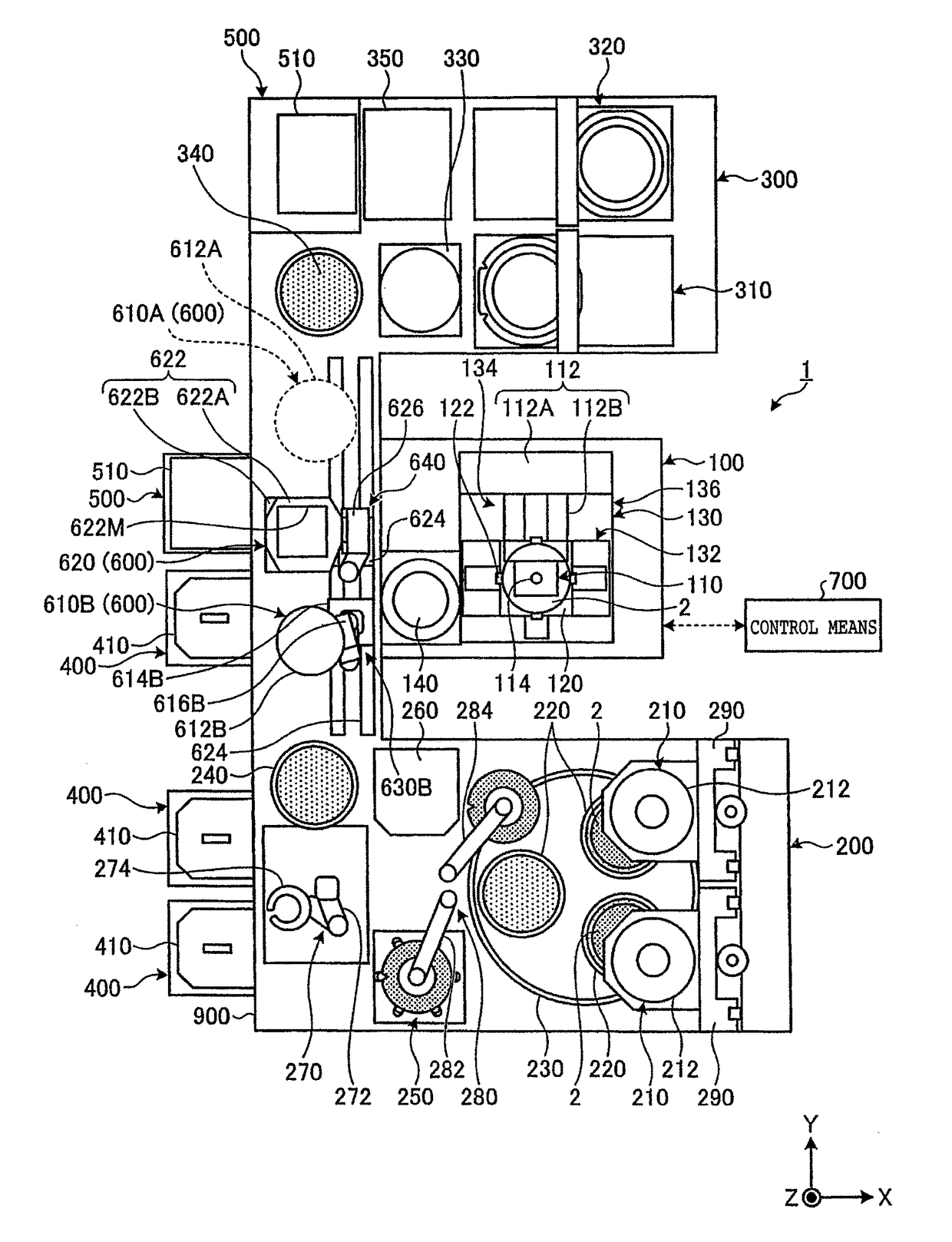
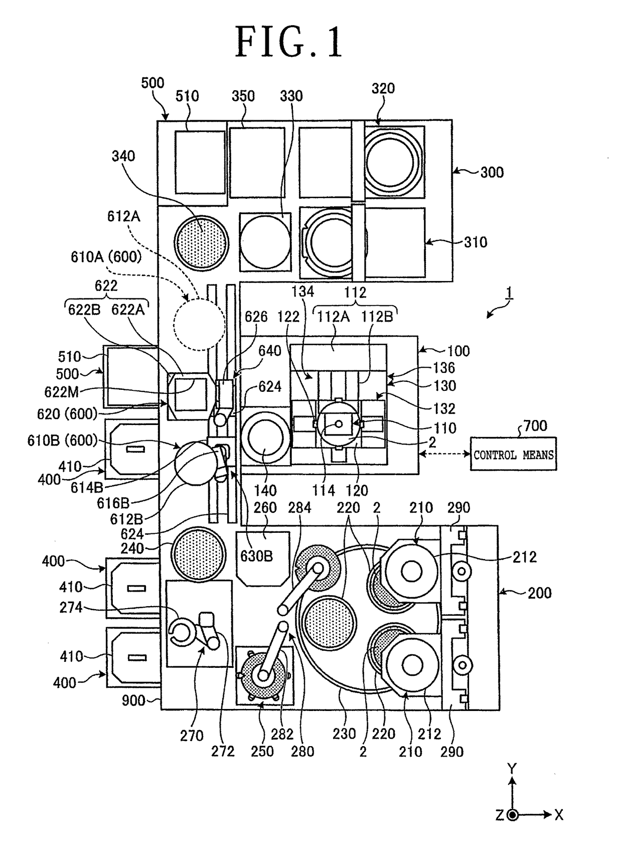
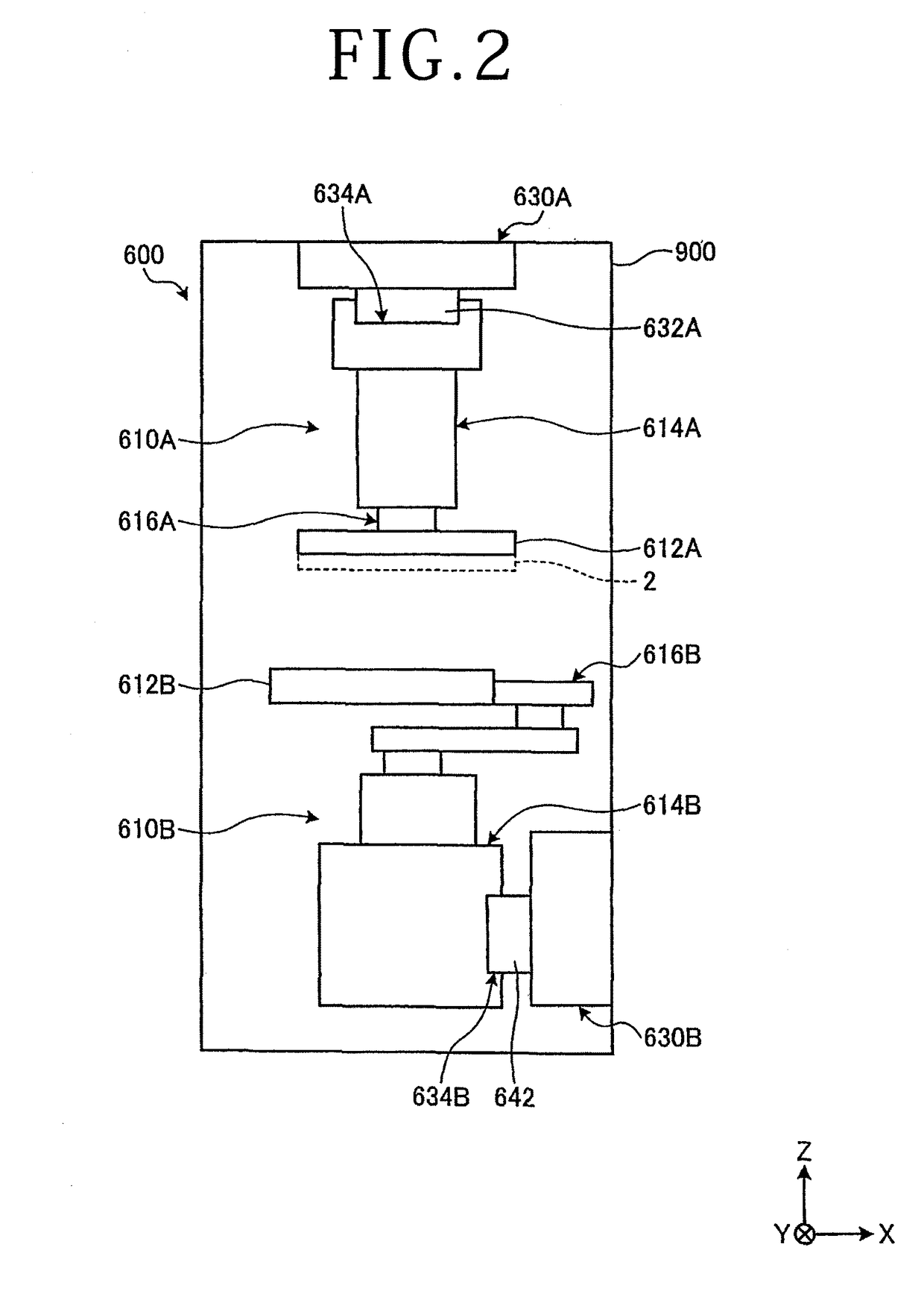
[0034]An embodiment according to the present invention will be described below with reference to the drawings. However, the present invention is not limited thereto. Constituent elements of the embodiment to be described below can be combined as appropriate. Furthermore, part of the constituent elements is not used in some cases. In the following description, an XYZ orthogonal coordinate system will be set and the positional relationship among the respective parts will be described with reference to this XYZ orthogonal coordinate system. The direction parallel to the X-axis in a horizontal plane is defined as the X-axis direction and the direction parallel to the Y-axis orthogonal to the X-axis in the horizontal plane is defined as the Y-axis direction. The direction parallel to the Z-axis orthogonal to each of the X-axis and the Y-axis is defined as the Z-axis direction. The XY-plane including the X-axis and the Y-axis is parallel to the horizontal plane. The Z-axis direction ortho...


PUM


Abstract

A wafer processing system includes a laser processing apparatus, a grinding apparatus, a tape sticking apparatus, a first cassette placement part, a second cassette placement part, a conveying unit that conveys a wafer, and a controller that controls the respective constituent elements. The controller includes a first processing program instructing section that conveys a wafer unloaded from a first cassette in order of the laser processing apparatus, the grinding apparatus, the tape sticking apparatus, and a second cassette and sequentially carries out processing by each apparatus for the one wafer, and a second processing program instructing section that conveys the wafer unloaded from the first cassette in order of the grinding apparatus, the laser processing apparatus, the tape sticking apparatus, and the second cassette and sequentially carries out processing by each apparatus for the one wafer.

Description

BACKGROUND OF THE INVENTIONField of the Invention[0001]The present invention relates to a wafer processing system.Description of the Related Art[0002]As methods for processing a wafer having a front surface on which devices are formed in plural regions partitioned by planned dividing lines, grinding processing by a grinding apparatus, laser processing by a laser processing apparatus, tape shift-sticking processing by a tape sticking apparatus, and so forth are known (refer to Japanese Patent Laid-open No. 2011-091293).[0003]In the case of dividing a wafer along planned dividing lines to manufacture plural device chips, treatment of thinning the wafer by grinding the back surface of the wafer by using the grinding apparatus, treatment of irradiating the wafer with a laser beam by using the laser processing apparatus, processing of sticking a dicing tape to the wafer by using the tape sticking apparatus, and so forth are carried out. The wafer thinned by the grinding apparatus is conv...

Claims


Application Information

Patent Timeline
IPC IPC(8): H01L21/67H01L21/677G05B19/27
CPCH01L21/6719H01L21/67282H01L21/67092H01L21/67132G05B2219/45031G05B19/27G05B2219/2627G05B2219/40623H01L21/6773B23K26/38H01L21/3043H01L21/67706H01L21/67219H01L21/67745H01L21/02013H01L21/268H01L21/673H01L21/67763H01L21/6836H01L21/76H01L21/78
Inventor TOGASHI, KENTSUKAMOTO, MASAHIRO
Owner DISCO CORP
Learn More