Unlock instant, AI-driven research and patent intelligence for your innovation.

Remote robotic actuation of a transeopagel echocardiography probe

a robotic actuator and echocardiography technology, applied in the field of transeesophageal echocardiography, can solve the problems of time-consuming and complex procedures, such as mitral clip deployment or transcatheter aortic valve replacement (“tavr”), fatigue and poor visualization, and poor visualization by echocardiographers

Active Publication Date: 2017-12-21
KONINKLJIJKE PHILIPS NV
View PDF12 Cites 1 Cited by
  • Summary
  • Abstract
  • Description
  • Claims
  • Application Information

AI Technical Summary

Benefits of technology

The present invention provides a remote robotic actuation system that allows for the remote control of a robotic workstation and a robotic actuator, which in turn controls a probe for ultrasound imaging. The system includes a replica control tool that can be used with existing robotic actuators and can be quickly disengaged if the medical professionals decide to return to manual operation of the probe. The main technical effects of the invention include improved precision and stability during ultrasound imaging procedures, increased operational flexibility for medical professionals, and reduced risk of injury during procedures.

Problems solved by technology

Exemplar procedures, such as mitral clip deployments or transcatheter aortic valve replacements (“TAVR”), can be time consuming and complex.
In practice, the operating conditions of FIG. 1 present several challenges.
The first challenge is fatigue and poor visualization.
This can lead to fatigue and poor visualization by echocardiographer 13 during long procedures.
Given the difficultly interpreting a 3D ultrasound volume, and the different co-ordinate systems displayed by the x-ray and ultrasound systems, it can be challenging for echocardiographer 13 to understand the intentions of cardiologist 15.

Method used


Image

  • Remote robotic actuation of a transeopagel echocardiography probe
  • Remote robotic actuation of a transeopagel echocardiography probe
  • Remote robotic actuation of a transeopagel echocardiography probe

Examples


Embodiment Construction

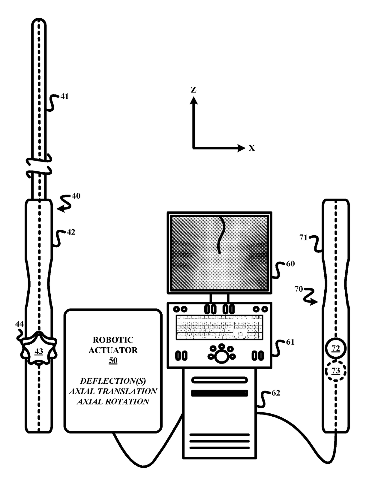
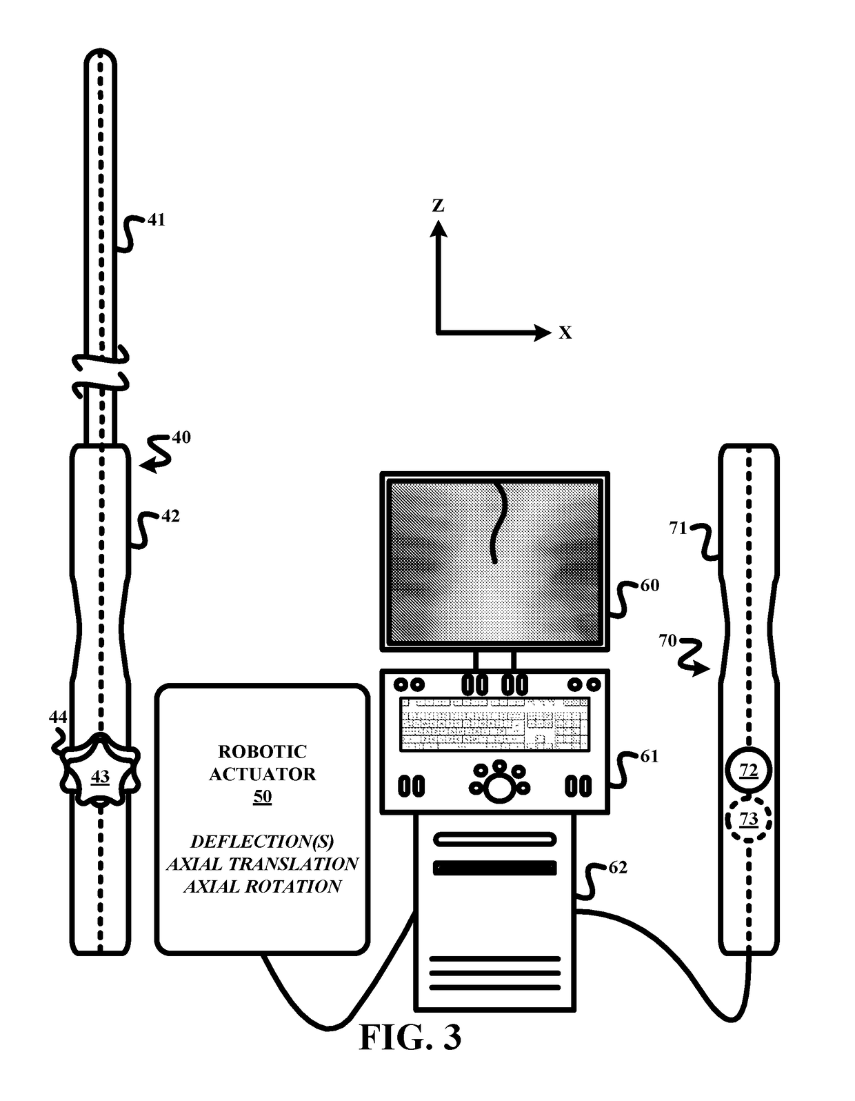
[0017]To facilitate an understanding of the present invention, exemplary embodiments of a robotic actuation system of the present invention and various components therefore will now be described in the context of a remote control actuation of a TEE probe as shown in FIG. 3. From these descriptions, those having ordinary skill in the art will appreciate how to apply the principles of a robotic actuation system of the present invention to any suitable designs of ultrasound probes for any type of procedure as well as other tendon driven flexible interventional tools (e.g., a catheter, an endoscope, a colonoscope, a gastroscope, a bronchosope etc.).

[0018]For purposes of the present invention, the terms of the art including, but not limited to, “deflection”, “joystick”, “accelerometer”, “light emitting diode”, “actuation”, “robotic”, “robotic actuator”, “workstation”, “input device” and “electromechanical device” are to be interpreted as known in the art of the present invention.

[0019]Re...


PUM


Abstract

A replica control tool (70) for remotely controlling a control handle (71) of an interventional tool (e.g., a probe, a catheter and a flexible scope) robotically controlled by a robotic actuator (50). The replica control tool (70) employs a replica control handle (71) substantially being a replica of a structural configuration of the control handle (71) of the interventional tool, and a control input device (72) (e.g., a joystick or a trackball) movable relative to the replica control handle (71). The replica control tool (70) further employs a robotic actuator controller (75) for remotely controlling the robotic actuator (50) in response to any movement of the control input device (72) relative to the replica control handle. The replica control tool (70) may further employ an electromechanical device (73) (e.g., an accelerometer) co-rotatable with the replica control handle (71) whereby the controller (75) remotely controls the robotic actuator (50) in response to a rotation of the electromechanical device (73).

Description

FIELD OF THE INVENTION[0001]The present invention generally relates to transeesophageal echocardiography (“TEE”) probes. The present invention specifically relates to a remote robotic actuation of the TEE probe during an interventional procedure.BACKGROUND OF THE INVENTION[0002]Transeesophageal echocardiography is commonly used to visualize cardiac anatomy and interventional devices during treatment for structural heart disease (“SHD”). FIG. 1 shows a typical distribution of theatre staff within a lab room 10a having an ultrasound workstation 11 and an x-ray scanner, of which a c-arm 12 is shown. During a SHD operation, an echocardiographer 13 holds a TEE probe 14, which passes through a mouth of a patient 16 into an esophagus to visualize a heart of patient 16. A cardiologist 15 is located on an opposite side of x-ray c-arm 12 and an operating table 17. Cardiologist 15 navigates interventional devices (not shown) (e.g., catheters and guidewires) from arterial incisions into the hea...

Claims


Application Information

Patent Timeline
IPC IPC(8): A61B34/37A61B8/12A61B8/00B25J13/02A61B34/00A61B18/00A61B34/30A61B90/00
CPCA61B34/37A61B34/74A61B8/12A61B2090/3784B25J13/02A61B2018/00303A61B2034/301A61B8/467
Inventor REINSTEIN, ARYEH LEIBPOPOVIC, ALEKSANDRANOONAN, DAVID PAUL
Owner KONINKLJIJKE PHILIPS NV