Sintered friction material for a friction lining

Active Publication Date: 2017-12-21
HOERBIGER ANTRIEBSTECHN HLDG
View PDF1 Cites 4 Cited by
  • Summary
  • Abstract
  • Description
  • Claims
  • Application Information

AI Technical Summary

Benefits of technology

[0010]It is the object of the invention to provide a sintered

Problems solved by technology

However, the common hard materials such as tungsten carbide are not sufficiently wetted by the metallic solders used in sintered friction materials.
Due to the low temperatures used during the production of friction linings and the short dwelling ti

Method used


Image

  • Sintered friction material for a friction lining

Examples


examples 1 to 4

[0044]To produce sintered friction materials, powder blends having the composition stated in the following table are provided. The powder blends are scattered onto a planar steel sheet with a thickness of 1.2-2.2 mm and a diameter of 70 to 110 mm and kept at a temperature of 830 to 840° C. in the sintering furnace.

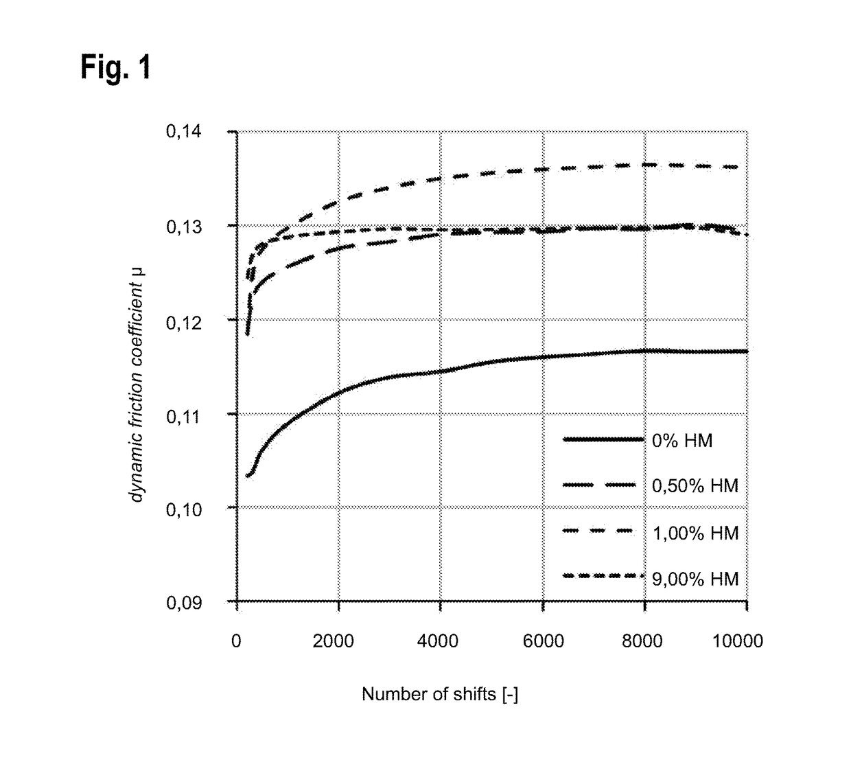
[0045]The friction linings made of the sintered friction materials that were thus obtained were compacted to a thickness of 450 to 500 μm, and the friction body was tested on a p-comp clutch and synchronizer test stand of the company Horbiger with steel as a friction surface counterpart. A sliding speed of 2 to 4 m / s with a compression of 2 to 4 MPa during oil flow at an oil temperature of 80° C. was selected. The development of the friction coefficient was determined via 10,000 successive shifts at various load levels.

[0046]FIG. 1 shows the development of the friction coefficient of the friction materials tested. The addition of sintered cemented carbide results in a fric...


PUM

PropertyMeasurementUnit
Grain sizeaaaaaaaaaa
Fractionaaaaaaaaaa

Abstract

A sintered friction material comprises a metallic matrix and granular constituents embedded in the matrix. The metallic matrix comprises a copper base alloy. The friction material is characterized in that the granular constituents comprise at least one sintered cemented carbide in a proportion of up to 9 weight percent, based on the total weight of the friction material. Furthermore, a friction body, in particular for clutches and brakes, that comprises a friction lining with at least one layer made of the sintered friction material, and a method for the production of a friction lining with the sintered friction material are described.

Description

FIELD OF THE INVENTION[0001]The invention relates to a sintered friction material for a friction lining, in particular a friction material for oil operation. Furthermore, the invention relates to a method for the production of a friction lining made of the sintered friction material, a friction body including the friction lining, and the use of the sintered friction material as a friction lining in a friction body, in particular for clutches and brakes.TECHNICAL BACKGROUND[0002]Friction materials have been widely used in drive technology, in particular in clutches, gears or brakes. The friction coefficient of the friction materials is intended to be as high and constant as possible.[0003]Production of friction linings based on sintered friction materials is cost-effective. In particular foil technology and scatter-sintering processes are used. In foil technology, suitable powder blends are pre-pressed by pressing tools into thin rings which are then sintered onto an optionally pre-t...

Claims


Application Information

Patent Timeline
IPC IPC(8): F16D69/02C22C29/02B22F3/10C22C1/05C22C1/04B22F7/04
CPCF16D69/027C22C29/02C22C1/05C22C1/0425B22F3/10B22F7/04F16D2200/0082B22F2301/30B22F2302/10B22F2302/40F16D2200/0026F16D2200/0043F16D2200/0052B22F2301/10C22C9/00C22C32/0052B22F7/08C22C1/1084B22F2999/00B23K35/262B23K35/302C22C29/08C09K3/14
Inventor CSANADI, ZOLTANTOURNERET, BRUNOECHTLER, PETERFUERGUTH, WERNEROHR, ANDREASSCHNABEL, ANDREAS
Owner HOERBIGER ANTRIEBSTECHN HLDG
Why Eureka
Try Eureka