Dialysis Water Purification System

a technology of water purification system and dialysis, applied in the nature of treatment water, multi-stage water/sewage treatment, membranes, etc., can solve the problems of not being able to know when the appropriate backwash operation occurred, unable to accommodate multiple backwashing tanks at the same time, etc., to prevent improper operation

Active Publication Date: 2017-12-28
GILLESPIE KEVIN C
View PDF4 Cites 3 Cited by
  • Summary
  • Abstract
  • Description
  • Claims
  • Application Information

AI Technical Summary

Benefits of technology

[0008]The present invention overcomes the disadvantages of the prior art by providing a control system for a pre-treatment system used to supply purified water to dialysis equipment having a plurality of sensors for interacting with the pre-treatment system and preventing improper operation thereof, thus assuring patient safety and health.
[0009]The invention includes a controller and operator interface for monitoring the pre-treatment system, which typically includes a number of filtration tanks for treating supply water, removing contaminants unsuitable for use in dialysis systems. The controller is operatively connected to a metering pump that supplies reducing agent to water supply 1 to remove oxidants from the supply water and scavenge oxygen, thereby reducing the chloride and chloramine levels of the supply water.
[0010]The controller is also operatively connected to a plurality of sensors for measuring the temperature, oxidation-reduction potential (ORP) and pH of the supply water at multiple points in the pre-treatment system. The controller can then adjust the amount of reducing agent injected into the water supply to accurately control the ORP / pH levels of the supply, thereby providing consistent, clean, de-chlorinated water to a final purification system for use in hemodialysis stations.

Problems solved by technology

However, these timer-activated systems suffer from a great number of disadvantages.
Initially, unless an operator is actually present at the time the backwash mode of operation is occurring, there is no way to know that the appropriate backwash operation occurred.
Additionally, since most dialysis water systems employ multiple filtration tanks such as multi-media filters, granular activated carbon filters, and water softeners, these tanks must be backwashed individually rather than simultaneously since the flow of water required for a backwash or rinse cycle is quite high, and most water supply systems can't accommodate multiple tanks backwashing simultaneously since a reduced water flow rate would not provide sufficient backwash or rinse flow.
When timer-actuated backwash operation is used, if an operator times more than one filtration tank to backwash in the same time period, the water flow rates to each tank may be insufficient to provide proper contaminant reductions.
Further compounding this problem is that when backwash operations occur late at night, an operator may not be present to determine that an incorrect backwash operation has occurred, i.e., that two or more tanks have backwashed simultaneously.
In this situation dialysis water system operation may be suboptimal or indeed hazardous to patients since the filtration tanks are not sufficiently cleaned to remove contaminants from the water.

Method used


Image

  • Dialysis Water Purification System
  • Dialysis Water Purification System
  • Dialysis Water Purification System

Examples


Embodiment Construction

)

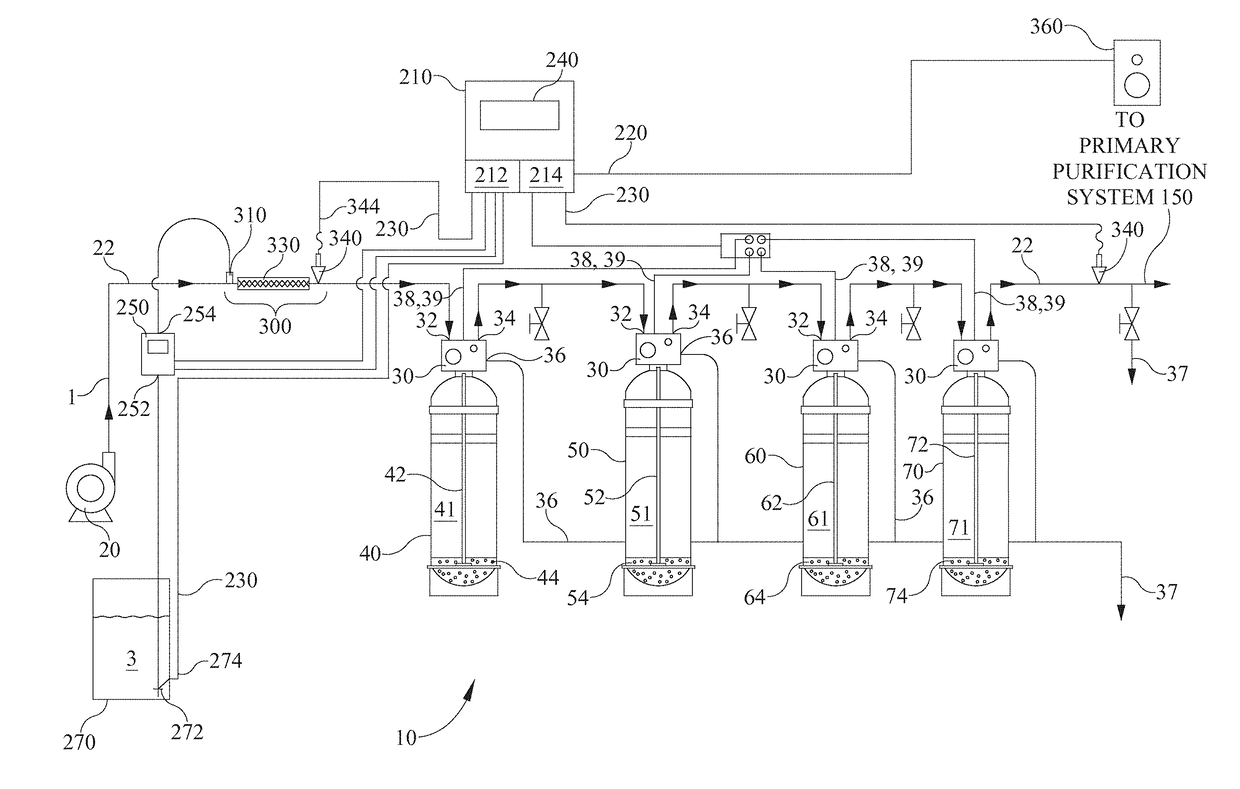
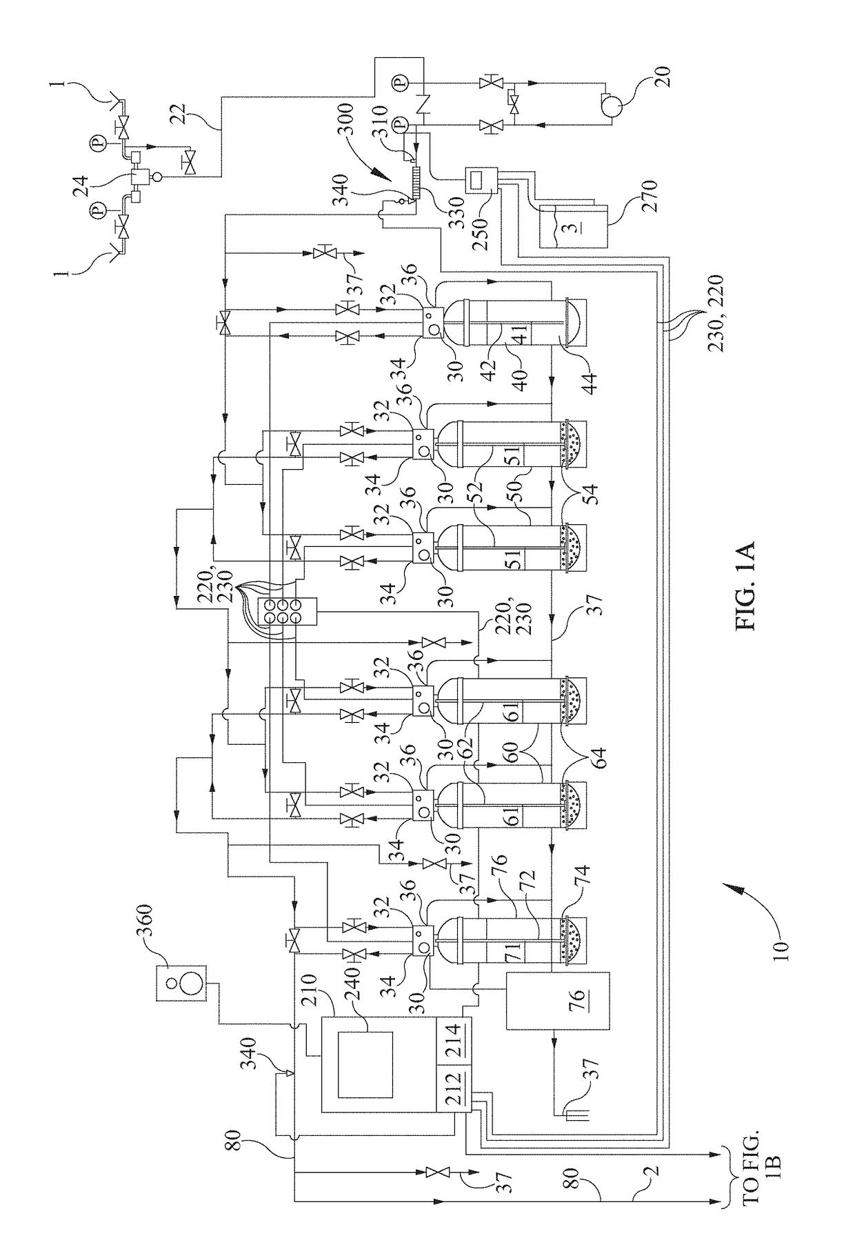
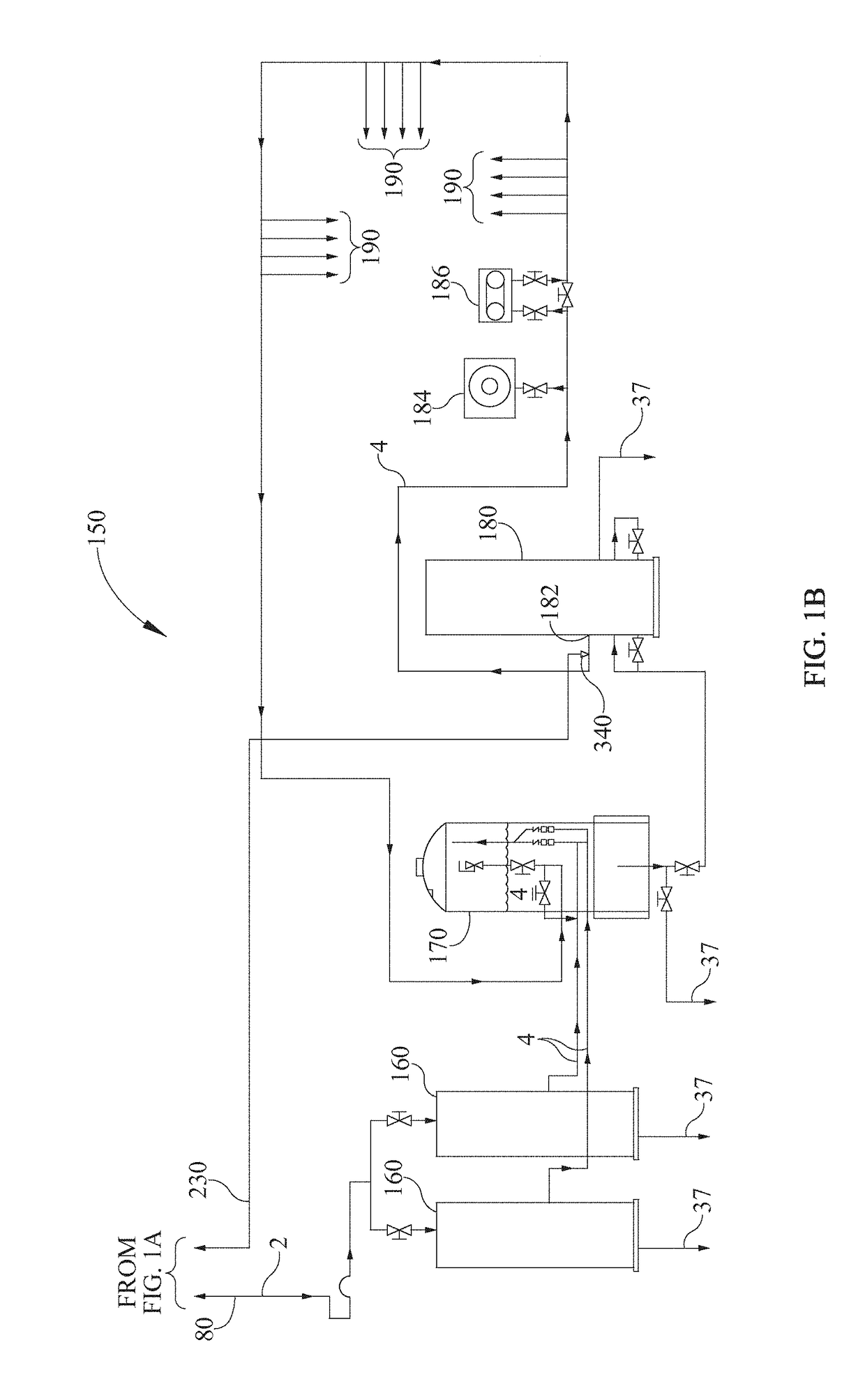
[0017]Referring now to FIGS. 1A-3 and in accordance with one embodiment of the present invention, a control system 200 is provided for operating and monitoring a dialysis water pre-treatment system 10 that is used to produce de-chlorinated and softened water for a primary purification system 150, that in turn supplies purified water for use in a plurality of dialysis stations 190.

[0018]Referring primarily to FIG. 2, an exemplary pre-treatment system 10 is depicted having a supply pump 20 for pressurizing and supplying a source of supply water 1 to system 10 through a supply line 22 and then through a plurality of media filtration and treatment tanks. Water 1 flows through supply line 22 into a series of filtration and / or softening tanks. Initially, supply line 22 is in fluid communication with a control valve 30 provided on a multi-media filtration tank 40, that is used as a first stage filter to remove contaminants from supply water 1. Filtration tank 40 comprises filtration media...


PUM


Abstract

The invention comprises a control system for monitoring and operating an existing supply water pre-treatment system for supplying de-chlorinated water to dialysis purification systems. The invention includes a controller and an operator interface for programming and interacting with said control systems. The invention further includes an injection assembly having a flow turbine sensor, a reducing agent injector, and an ORP / pH sensor for monitoring and controlling ORP / pH levels of said supply water.

Description

CROSS-REFERENCE TO RELATED APPLICATIONS[0001]The present application claims priority to and benefit of, under 35 U.S.C. §120, U.S. nonprovisional patent application Ser. No. 12 / 945,471, filed Nov. 12, 2010 which claims the benefit of U.S. Provisional Patent Application Ser. No. 61 / 261,119, filed Nov. 13, 2009, entitled “Dialysis Water Purification System”.BACKGROUND OF THE INVENTIONField of the Invention[0002]The present invention relates generally to a water purification system and more specifically to a system and method for monitoring and cleaning a water pre-treatment system including backwash and regeneration of all media tanks used to provide water to a primary purification system.Description of the Related Art[0003]Dialysis systems for treatment of patients with kidney disorders are in widespread use throughout the health care industry. These systems all require a constant source of purified water that removes organic and inorganic substances and microbial contaminants from t...

Claims


Application Information

Patent Timeline
Patent Type & Authority Applications(United States)
IPC IPC(8): B01D61/12
CPCC02F2209/40C02F2209/04C02F2209/06B01D61/12B01D2321/04C02F1/001C02F1/008C02F1/283C02F1/441C02F1/70C02F1/76C02F9/00C02F2103/026C02F2209/005C02F2303/16C02F2303/185B01D61/025B01D61/243B01D61/32B01D65/02B01D65/027B01D2311/04B01D2311/18B01D2317/04B01D2313/60B01D2311/2649B01D2311/16B01D2311/2626B01D2311/2623
Inventor GILLESPIE, KEVIN C.
Owner GILLESPIE KEVIN C
Why Eureka
Try Eureka