Fiber-optic fluorescence sensor for highly sensitive and specific detection of chemical hazards

a fluorescence sensor and fiber optic technology, applied in the field of fiber optic sensors, can solve the problems of heavy metal ions such as lead ions or copper ions having deleterious effects on human health, contaminating drinking water or industrial waste water, and being detected in trace amounts

Inactive Publication Date: 2017-12-28
SPI SECURITY PROTECTION INT SECURITE PROTECTION INT
View PDF7 Cites 2 Cited by
  • Summary
  • Abstract
  • Description
  • Claims
  • Application Information

AI Technical Summary

Benefits of technology

[0008]This sensor is suitable for a wide range detection of fluorescence radiation, which can be used for various chemical or biological targets. The fiber sensor can be optimized for a specific working wavelength, which is usually defined by the properties of the chosen chemical probe, and therefore can be utilized for detection of many different targets. This makes the sensor platform potentially extremely cost-effective.
[0036]Multi-mode: In an optical fiber, a light beam can be decomposed into fundamental modes of propagation, in a way analogous to a signal decomposed into sines of different frequencies. If the optical fiber has a narrow core, only one mode can propagate (i.e., it is single-mode). If the core is large enough, various modes can propagate within the fiber, i.e., the fiber is thereby a multi-mode fiber. Some modes may have properties that do not allow them to propagate into the fiber (evanescent or leaky modes), while others can propagate without significant loss (bound-core modes). Perturbations in or on the optical fiber break the perfect circular geometry and allows mode conversion of the light signal, i.e., energy that is propagating in a mode can be transferred to another mode.

Problems solved by technology

Heavy metal ions such as lead ions or copper ions can have deleterious effects on human health even at low concentrations.
Heavy metal ions can be a source of dangerous contamination of drinking water or in industrial waste water, and as a result need to be detected in trace amounts.
This makes the sensor platform potentially extremely cost-effective.

Method used


Image

  • Fiber-optic fluorescence sensor for highly sensitive and specific detection of chemical hazards
  • Fiber-optic fluorescence sensor for highly sensitive and specific detection of chemical hazards
  • Fiber-optic fluorescence sensor for highly sensitive and specific detection of chemical hazards

Examples


Embodiment Construction

[0074]There is described herein a corrugated fiber grating optical fiber used as a sensor for measuring a light signal from a fluorescible sample.

Intrinsic Developed Fiber Sensor: Corrugated Fiber Grating

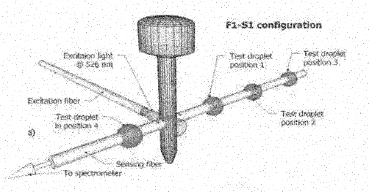
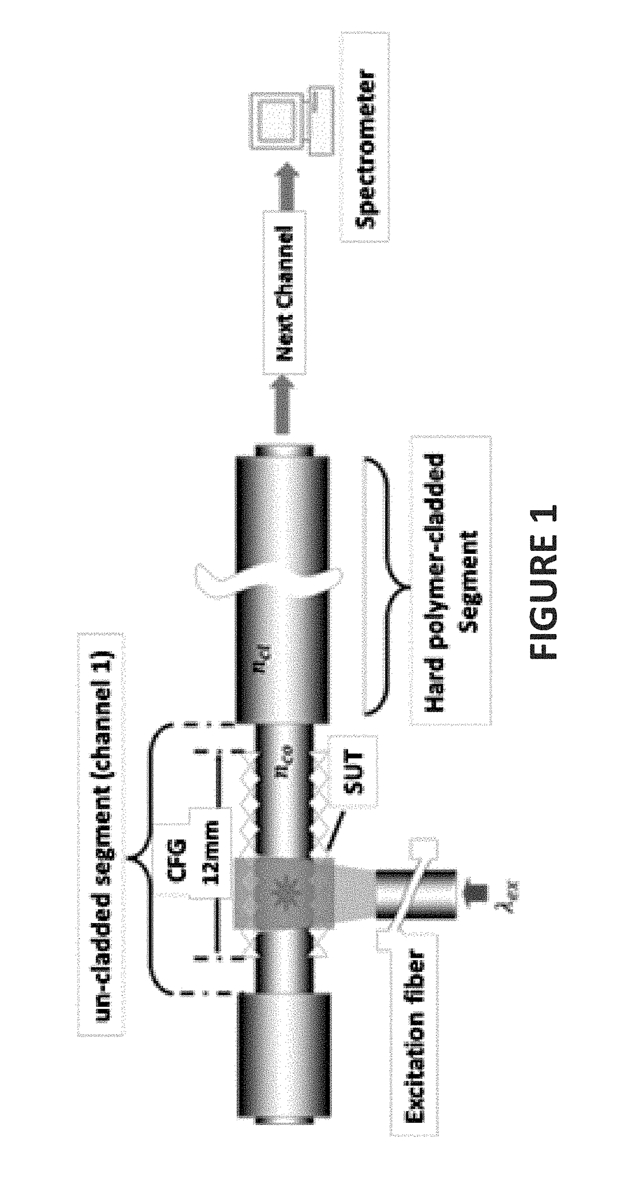
[0075]The corrugated fiber grating optical fiber fluorescence configuration has been determined as being efficient and very well adapted for the considered applications. It uses the side-wall of the fiber and a mechanism to couple refracting rays to the bound rays. A type of grating called corrugated fiber grating (CFG) is introduced for the repeatability and improvement of the sensor.

[0076]The proposed multi-segment fluorescence fiber probe is shown in FIG. 1. Comparing to traditional fiber-optic fluorescence probes, there are several differences which distinguish this probe as a bulk fluorescence probe that uses the side-wall of the fiber rather than its end-face. In this probe a small volume of the sample is needed to take measurements. Unlike the tapered or evanescent-wave fluor...


PUM

PropertyMeasurementUnit
sizeaaaaaaaaaa
depthaaaaaaaaaa
depthaaaaaaaaaa

Abstract

There is described a fiber-optic sensor for measuring a light signal from a fluorescible sample comprising heavy metal ions, for example. The fiber-optic sensor comprises an optical fiber having a side surface by which the light signal from the fluorescible sample is inputted. The optical fiber is corrugated to form at least two gratings on the side surface of the optical fiber. Each grating comprises periodically longitudinally spaced-apart valleys on the surface of the optical fiber, and is longitudinally spaced apart from any other grating of the at least two gratings.

Description

BACKGROUND(a) Field[0001]The subject matter disclosed generally relates to fiber optic sensors. More specifically, it relates to sensors for the measurement of chemical concentrations of chemical hazards.(b) Related Prior Art[0002]There exist various sensors for detecting various chemical components.[0003]A critical aspect of chemical compound detection is the measurement of heavy metal ions in drinking water. Heavy metal ions such as lead ions or copper ions can have deleterious effects on human health even at low concentrations. Since everyone can be affected, solutions for detection of these harmful substances should be widespread and therefore cheap to fabricate and easy to operate.[0004]Such sensors should also have sufficient sensitivity since the substances at issue can be harmful even at very low concentrations that can be hard to detect without sophisticated equipment.SUMMARY[0005]There are disclosed fiber-optic sensors based on fluorescence detection, especially for chemic...

Claims


Application Information

Patent Timeline
Patent Type & Authority Applications(United States)
IPC IPC(8): G01N33/20G02B6/02G01N21/64G02B6/14
CPCG01N33/20G02B6/14G02B6/0208G01N21/6404G01N2021/6417G01N2021/6484G01N21/645G01N33/1813G02B6/02066
Inventor CHINIFOROOSHAN, YASSERBOCK, WOJTEK
Owner SPI SECURITY PROTECTION INT SECURITE PROTECTION INT
Why Eureka
Try Eureka