Needle and manufacturing method thereof

a manufacturing method and needle technology, applied in the field of needles, can solve problems such as significant pain in patients, and achieve the effects of suppressing damage in the puncture route, preventing pocket effect, and excellent infection control

Inactive Publication Date: 2018-01-04
ASAHI KASEI MEDICAL CO LTD +2
View PDF7 Cites 0 Cited by
  • Summary
  • Abstract
  • Description
  • Claims
  • Application Information

AI Technical Summary

Benefits of technology

[0037]According to the present invention, it is possible to effectively prevent a pocket, being a potential source of infection, from being formed in a wall of a puncture route and it is therefore possible to provide excellent infection control. It is also possible, during an operation of puncturing a blood vessel through the puncture route, to suppress damage in the puncture route and around the blood vessel. At the same time, the operation of puncturing the blood vessel can be simply performed in a short time. Furthermore, it is possible to alleviate pain involved in the operation of puncturing the blood vessel and is therefore possible to alleviate the burden on the patient. It is also possible to appropriately perform the operation of puncturing the blood vessel, regardless of an operator's experience or technique.

Problems solved by technology

Such puncture operation needs to be performed every time the blood purification treatment is conducted and causes a patient significant pain on each such occasion.

Method used


Image

  • Needle and manufacturing method thereof
  • Needle and manufacturing method thereof
  • Needle and manufacturing method thereof

Examples


example 1

[0102](Evaluation Test 1)

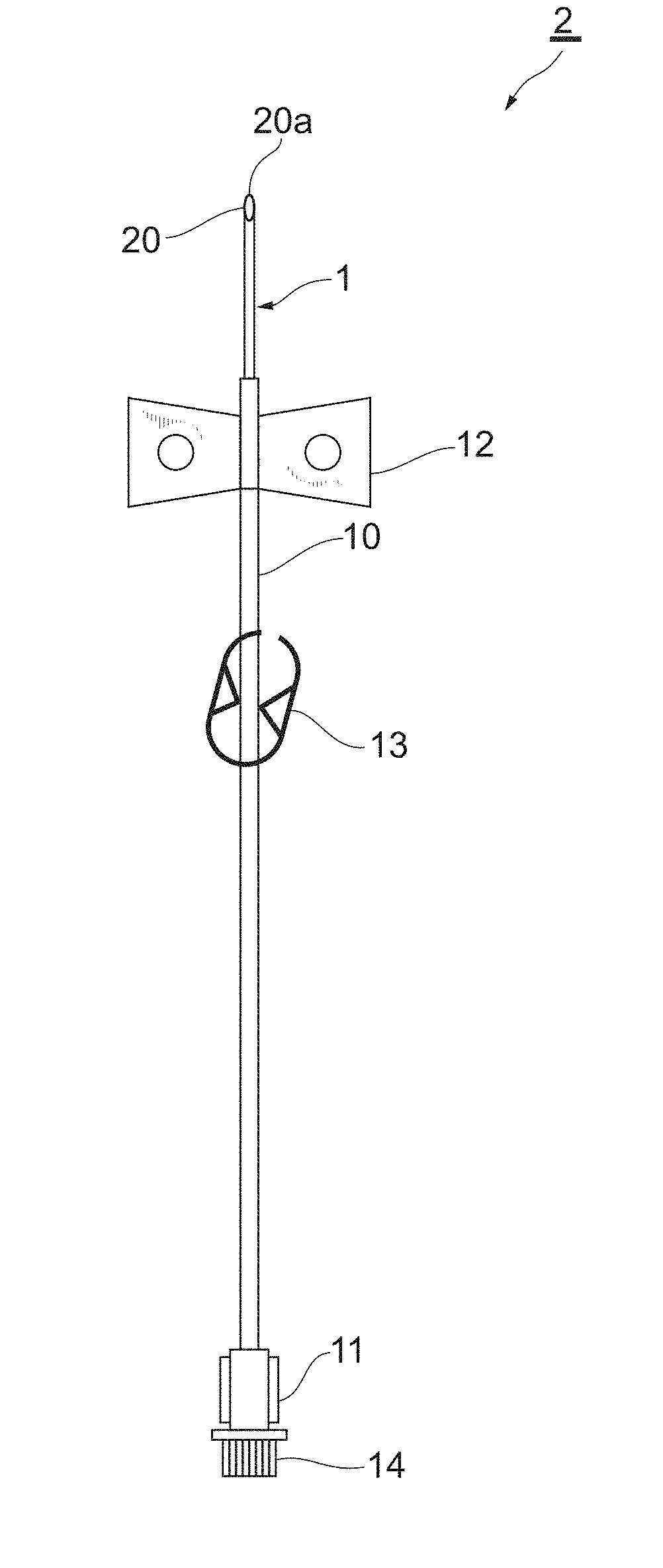
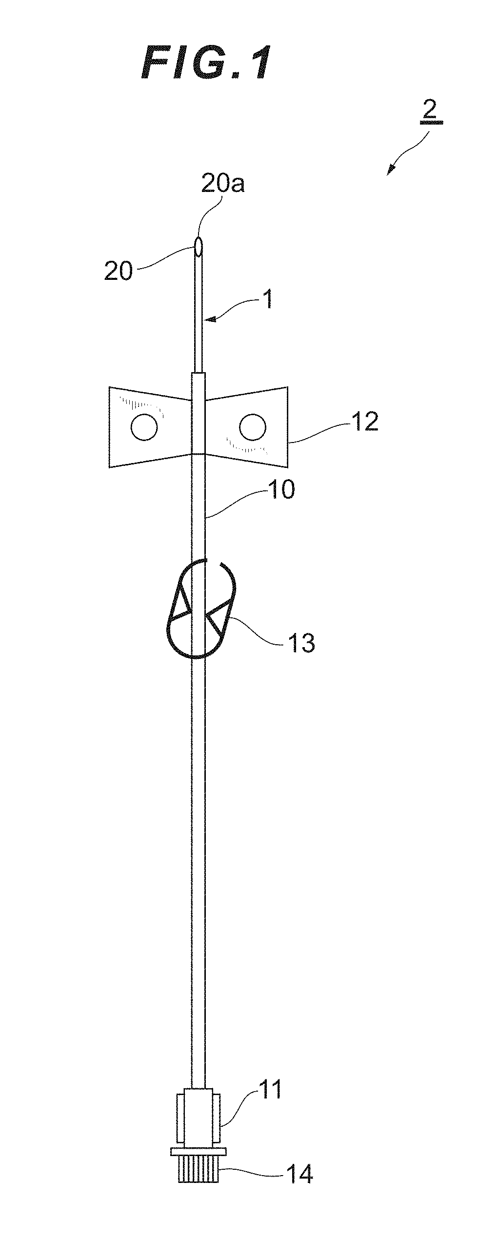
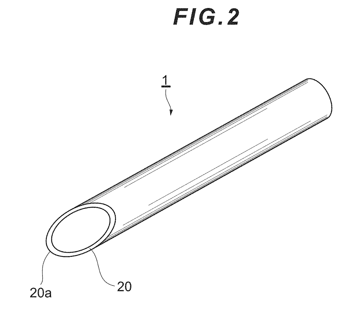
[0103]A needle elastic modulus nE was calculated for each sample of the dull needle 1 according to the present invention and a conventional dull needle. Sample 1 is a tubular dull needle made of Teflon (registered trademark) and having an outer diameter of 1.7 mm and an inner diameter of 1.3 mm. Sample 2 is a tubular dull needle made of polypropylene and having an outer diameter of 1.5 mm and an inner diameter of 1.1 mm. Sample 3 (comparative example) is a tubular dull needle made of stainless steel and having an outer diameter of 1.5 mm and an inner diameter of 1.2 mm. The shape of Samples 1 and 2 is shown in FIGS. 22A to 22C and the shape of Sample 3 is shown in FIG. 2. Samples 1 and 2 have the same shape, although they are made of different materials.

[0104]Samples 1 to 3 were subjected to a three-point bending test defined by JIS K 7171, under the conditions shown in Table 1.

TABLE 1Humidity23 ± 2° C.Humidity50 ± 5% RHTest ma-AG-X (manufacturedLoad cell50N...

example 2

[0111]A mold for producing a molded product using the ring gate 50 shown in FIG. 19 was designed and subjected to high-speed injection molding. From the resulting molded product, a dull needle 1 having a wall thickness of 1 mm, an outer diameter of 1.47 mm and a length of 41 mm could be prepared. The resulting dull needle 1 was free from short shot, flash and gate mark, and had a uniform wall thickness and smooth inner and outer surfaces. This was achieved by a configuration in which the pressure of the resin flowing from the runner 200 was increased in the ring gate 50 and the resin was allowed to immediately fill a needle portion. Such configuration could achieve filling despite the thin wall thickness of the dull needle 1, and was able to suppress variations in filling in the circumferential direction and prevent undesirable generation of flash.

[0112]A measurement of the flow rate was conducted on an integrally molded product of the dull needle 1 and the holding part 12.

[0113](Ev...


PUM

PropertyMeasurementUnit
deflection temperatureaaaaaaaaaa
elastic modulusaaaaaaaaaa

Abstract

The present invention suppresses the formation of a pocket in a wall of a puncture route when a dull needle is moved forward along the puncture route. In order to achieve such aim, the invention provides a needle to be inserted into a puncture route extending from skin to a blood vessel under the skin to puncture the blood vessel, wherein: the needle is formed in a tubular shape and has an inclined end face at a tip of the needle, the inclined end face being inclined relative to an axis of the needle, a tip end of the inclined end face defining an unsharp edge; the needle has a flexibility of needle elastic modulus nE=1-900 Nmm as defined by an equation to be set forth below; a material of the needle is a resin; and the needle is manufactured by injection molding using a ring-shaped gate.

Description

TECHNICAL FIELD[0001]The present invention relates to a needle to be inserted into a puncture route extending from skin to a blood vessel under the skin so as to puncture the blood vessel, as well as to a manufacturing method of such needle.BACKGROUND ART[0002]When blood purification treatment, such as dialysis treatment, is performed, a needle is inserted via a patient's skin so as to puncture a blood vessel and blood is collected and returned through the needle. Such puncture operation needs to be performed every time the blood purification treatment is conducted and causes a patient significant pain on each such occasion. Therefore, in order to reduce the pain produced when making a puncture, a so-called “buttonhole puncture method” has been used in recent years. In the buttonhole puncture method, an ordinary needle having high sharpness (an ordinary needle for initial puncture) is used to make a puncture during the first puncture operation to form a puncture route extending from...

Claims


Application Information

Patent Timeline
Patent Type & Authority Applications(United States)
IPC IPC(8): A61M5/32
CPCA61M5/329A61M2005/3247A61M2005/3284A61M2005/3212A61M5/158B29C45/2708A61M1/3661B29L2031/7544A61M1/14A61M25/0643B21G1/08A61M2207/00
Inventor SASAKI, MASATOMISHINZATO, TORUMARUYAMA, YASUYOSHIGENOBU, FUMITAKA
Owner ASAHI KASEI MEDICAL CO LTD
Why Eureka
Try Eureka