Near synchronous distributed hydraulic motor driven actuation system

Active Publication Date: 2018-01-04
PARKER-HANNIFIN CORP
View PDF6 Cites 12 Cited by
  • Summary
  • Abstract
  • Description
  • Claims
  • Application Information

AI Technical Summary

Benefits of technology

The present invention is about a system for controlling multiple actuators in an aircraft. It eliminates the need for torque tube routes and uses a common hydraulic power source to drive multiple actuators simultaneously, resulting in cost-efficient manufacturing and less weight in the aircraft. Additionally, it includes a method for controlling the movement of adjustable components of the aircraft by identifying the actuator that positionally leads the others and reducing hydraulic power to the motion control assembly of that actuator. This results in synchronous or near-synchronous motion of the actuators.

Problems solved by technology

Due to the thin wing design, the area along the spars of the wings may be congested such that routing of mechanical drive shafts, such as torque tubes, between the central power drive unit and actuators and between actuators may be difficult.
Using a multiple controller system may have complex wiring for the controllers and require more components than in other actuation systems.
Thus, the prior actuation system may have disadvantages with regards to system reliability, the overall weight of the system aboard the aircraft, the envelope of the aircraft, and the ability to perform maintenance on the system.

Method used


Image

  • Near synchronous distributed hydraulic motor driven actuation system
  • Near synchronous distributed hydraulic motor driven actuation system
  • Near synchronous distributed hydraulic motor driven actuation system

Examples


Embodiment Construction

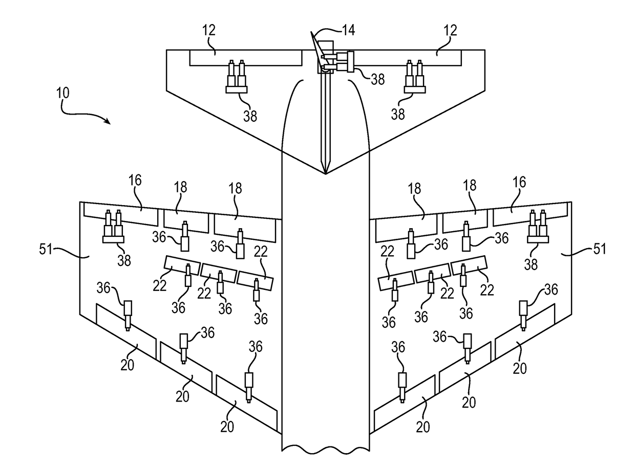
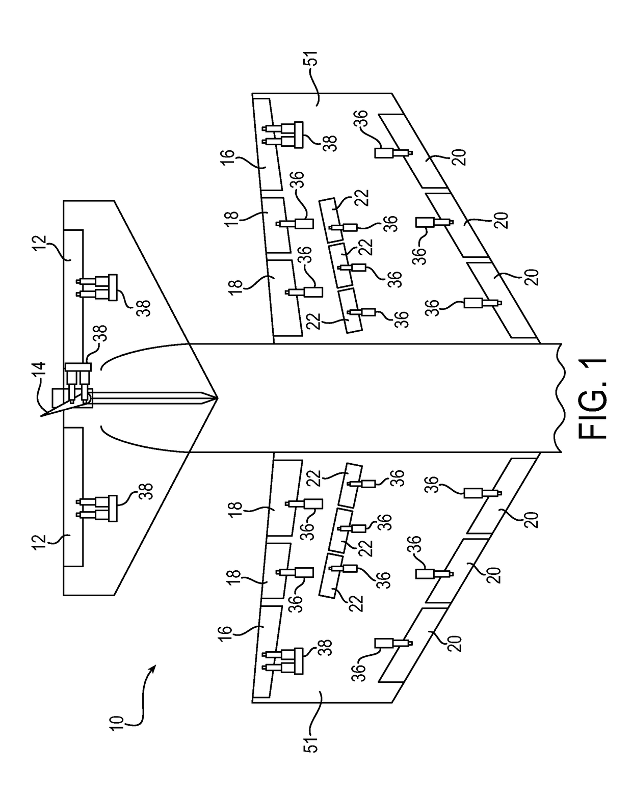
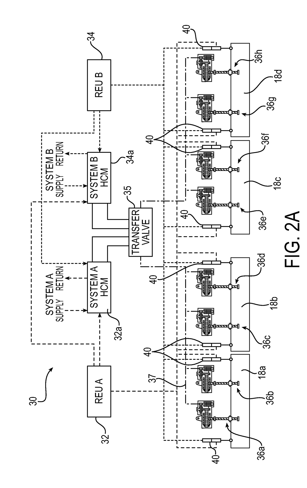
[0025]Aspects of the present invention relate to a distributed hydro-mechanical actuation system that includes multiple hydro-mechanical actuators intended to operate together in a synchronous (or near synchronous) manner. Each individual actuator may be powered by one or more hydraulic motors that are configured to have a high volumetric efficiency with a low velocity loss relative to the flow of hydraulic fluid. The group of actuators may be controlled from a single hydraulic control module that includes a pressure compensated flow control valve and a directional control valve or an electro-hydraulic servo valve type of open loop control in which the hydraulic flow rate is controlled to assure that the motors operate at a predetermined speed. The output of the actuators is maintained near synchronous over the applied load range within a volumetric efficiency (e.g. internal leakage) between motors over the operating range between a no-load and an operating point maximum load. The g...


PUM


Abstract

A control system may be used to control actuators that actuate movement of flight control surfaces of an aircraft. Each actuator is couplable to a flight control surface and includes a motion control assembly having a hydraulic motor and a drive path from the hydraulic motor to the flight control surface. Each hydraulic motor includes an extend port and a retract port. The system includes a hydraulic control module fluidly connected to the extend port and the retract port of each hydraulic motor and a controller operable to output hydraulic power from the hydraulic control module to the motion control assembly to actuate movement of the flight control surfaces. The controller is configured to identify an actuator that positionally leads the other actuators and reduce hydraulic power to the motion control assembly assigned to such actuator.

Description

FIELD OF INVENTION[0001]The present invention relates to a hydro-mechanical actuation drive system requiring the synchronous (or near synchronous) operation of multiple individual actuators.BACKGROUND[0002]Modern thin wing aircraft designs are aimed at optimizing fuel economy. Due to the thin wing design, the area along the spars of the wings may be congested such that routing of mechanical drive shafts, such as torque tubes, between the central power drive unit and actuators and between actuators may be difficult.[0003]Prior actuation systems may eliminate torque tube routes by providing individual servo-controlled electric actuators at each actuation station such that each station may use one or more motor controllers with associated motor commutation signals and loop closures. Using a multiple controller system may have complex wiring for the controllers and require more components than in other actuation systems. Thus, the prior actuation system may have disadvantages with regar...

Claims


Application Information

Patent Timeline
IPC IPC(8): B64D31/12F16H61/04F16H61/06F16H61/08
CPCB64D31/12F16H2061/085F16H61/061F16H61/0403B64C13/36B64C13/504B64C13/505F15B11/22F15B2211/6657F15B2211/8757F15B2211/7058F15B2211/3059F15B2211/31547F15B2211/20576F15B2211/6336F15B20/002F15B20/008F15B2211/30595F15B2211/7142F15B19/002F15B2211/7121F15B2211/3058F15B11/205F15B2211/415F15B2211/327F15B11/024F15B2211/782B64C9/16B64C9/22B64C9/323
Inventor POLCUCH, ERIC ALEXANDER
Owner PARKER-HANNIFIN CORP
Why Eureka
Try Eureka