Machine learning assisted reservoir simulation

a reservoir simulation and machine learning technology, applied in the field of electric, electronic and computer arts, can solve problems such as surface subsidence, damage to well equipment, and understanding and predicting subsidence at the surfa

Active Publication Date: 2018-01-04
IBM CORP
View PDF3 Cites 6 Cited by
  • Summary
  • Abstract
  • Description
  • Claims
  • Application Information

AI Technical Summary

Benefits of technology

[0010]Techniques of the present invention can provide substantial beneficial technical effects; e.g. dynamic reconfiguration, including switching a reservoir model, during a coupled workflow. Thus, an illustrative embodiment of the invention may advantageously help professionals in interdisciplinary areas making decisions in oil exploration analysis.

Problems solved by technology

One of the most challenging problems in the petroleum industry is the understanding and prediction of subsidence at the surface due to formation compaction that happens as a result of fluid withdrawal from the reservoir.
However, reservoir compaction may also reduce permeability, causing surface subsidence and damaging well equipment.
Subsidence phenomena can cause excessive stress at the well casing, which can result in casing buckling and / or casing sheer.
Subsidence phenomena can also cause excessive stress within the completion zone, where collapse of structural integrity could lead to loss of production (e.g., due to pressure decline).
Subsurface subsidence can result in problems at the wellhead or with pipeline systems and platform foundations.
Mudline subsidence can cause fault activation or movement, which in turn can result in reduced wellbore stability (e.g., due to concrete cracking) or subsea wellhead failures.
Unlike standard compaction drive simulation, there is no simple linear method to account for the effects of stress on permeability, especially for fractured systems, in which the changes of permeability might be directional, localized, and strongly nonlinear.
As a result, fluid flow in a porous medium under such scenarios cannot be simplified to compressibility or pressure dependent porosity / permeability changes.
Once coupling is completed using the selected model, if the coupling using the selected model leads to unsatisfactory results, the selected model is abandoned and a new (e.g., more complex) model is selected instead.

Method used


Image

  • Machine learning assisted reservoir simulation
  • Machine learning assisted reservoir simulation
  • Machine learning assisted reservoir simulation

Examples


Embodiment Construction

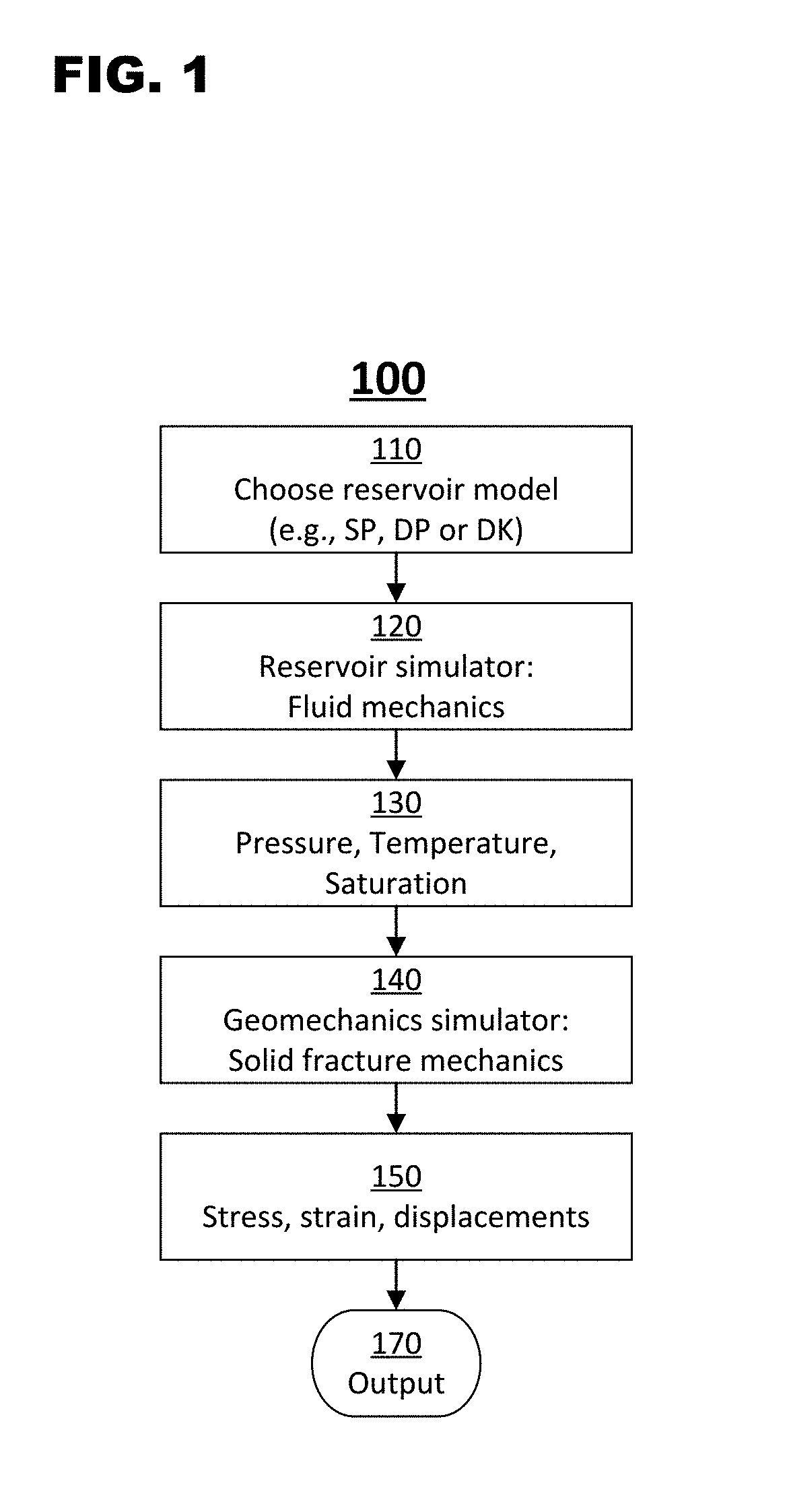
[0022]Known coupling algorithms include one-way coupling (1WC) and two-way coupling (2WC). FIG. 1 is a flowchart showing a conventional one-way coupling (1WC) algorithm 100. Algorithm 100 begins with the selection of a reservoir model in step 110. This selection may be made manually by a user or automatically by a computer. As discussed above, the selected reservoir model is used for all subsequent simulation, including reservoir simulation 120 and geomechanical simulation 140. The reservoir model may be selected from a group including single porosity (SP), dual porosity (DP), and dual permeability (DK). In step 120, the selected reservoir model is used by a reservoir simulator to analyze fluid mechanics thereby computing pressure, temperature, and saturation (PTS) values 130. The PTS values 130, as well as the selected reservoir model 110, are used in step 140 by a geomechanical simulator to analyze solid fracture mechanics thereby computing stress, strain, and displacement values ...


PUM


Abstract

An embodiment includes a method for use by at least one machine learning classifier. The method comprises the machine learning classifier obtaining one or more recent results from at least one geomechanical simulation; the machine learning classifier comparing the recent results to stored historical data; and, based on the comparing, the machine learning classifier deciding at least one reservoir model for use by at least one reservoir simulation.

Description

FIELD OF THE INVENTION[0001]The present invention relates to the electrical, electronic and computer arts, and, more particularly, to geomechanical simulation of a reservoir.BACKGROUND OF THE INVENTION[0002]One of the most challenging problems in the petroleum industry is the understanding and prediction of subsidence at the surface due to formation compaction that happens as a result of fluid withdrawal from the reservoir. In some oil fields (e.g., poorly compacted reservoirs), stress changes associated with reservoir compaction can have beneficial results on fluid recovery (e.g., oil and gas production).[0003]However, reservoir compaction may also reduce permeability, causing surface subsidence and damaging well equipment. Subsidence phenomena can cause excessive stress at the well casing, which can result in casing buckling and / or casing sheer. Subsidence phenomena can also cause excessive stress within the completion zone, where collapse of structural integrity could lead to los...

Claims


Application Information

Patent Timeline
Patent Type & Authority Applications(United States)
IPC IPC(8): G06F17/50G06N99/00G06N20/00
CPCG06N99/005G06F17/5009G01V99/005G06N20/00G06F30/20E21B41/00G01V11/00
Inventor BORREL, PAULKORMAKSSON, MATTHIASPAZ, CARMEN NILDA MENA
Owner IBM CORP
Why Eureka
Try Eureka