
Arrangement with a heat-insulating switch and a heat insulation

Active Publication Date: 2018-01-04
ROBERT BOSCH GMBH
View PDF0 Cites 0 Cited by
  • Summary
  • Abstract
  • Description
  • Claims
  • Application Information

AI Technical Summary

Benefits of technology

The invention is a battery with a switch that prevents thermal outflow when the switch is closed, save for when the battery is being discharged. This design prevents the switch from being actuated under load, reducing the risk of ignition. The switch is protected from welding or erosion, and the contacts are not overloaded. The battery also benefits from not losing heat during periods of inactivity, as this would normally happen. The switch can be controlled by the battery management system, and additional means can be used for current detection to prevent ignition. Overall, this design ensures the battery is safer and more reliable.

Problems solved by technology

Electrical leads having a low electrical resistance as a rule also exhibit low thermal resistance.
The problem of undesired heat loss or heat exchange thus increases as the conductive cross section increases.
In cases in which a large conductive cross section is necessary so that high electrical currents can be transported, a large heat loss can also be expected.
If the heat required for operation of the battery is generated by the battery itself, the energy required in order to compensate for the heat loss reduces the electrical energy that can be furnished to a load.
If an electrical discharge is intermittently interrupted, however, as is the case e.g. in an electric vehicle, the energy loss due to the heat loss can result in a loss of several percent of battery capacity.
It is thus not possible for the switch itself to constitute a thermal bridge, for example due to a thermally conductive housing.

Method used


Image

  • Arrangement with a heat-insulating switch and a heat insulation
  • Arrangement with a heat-insulating switch and a heat insulation
  • Arrangement with a heat-insulating switch and a heat insulation

Examples


Embodiment Construction

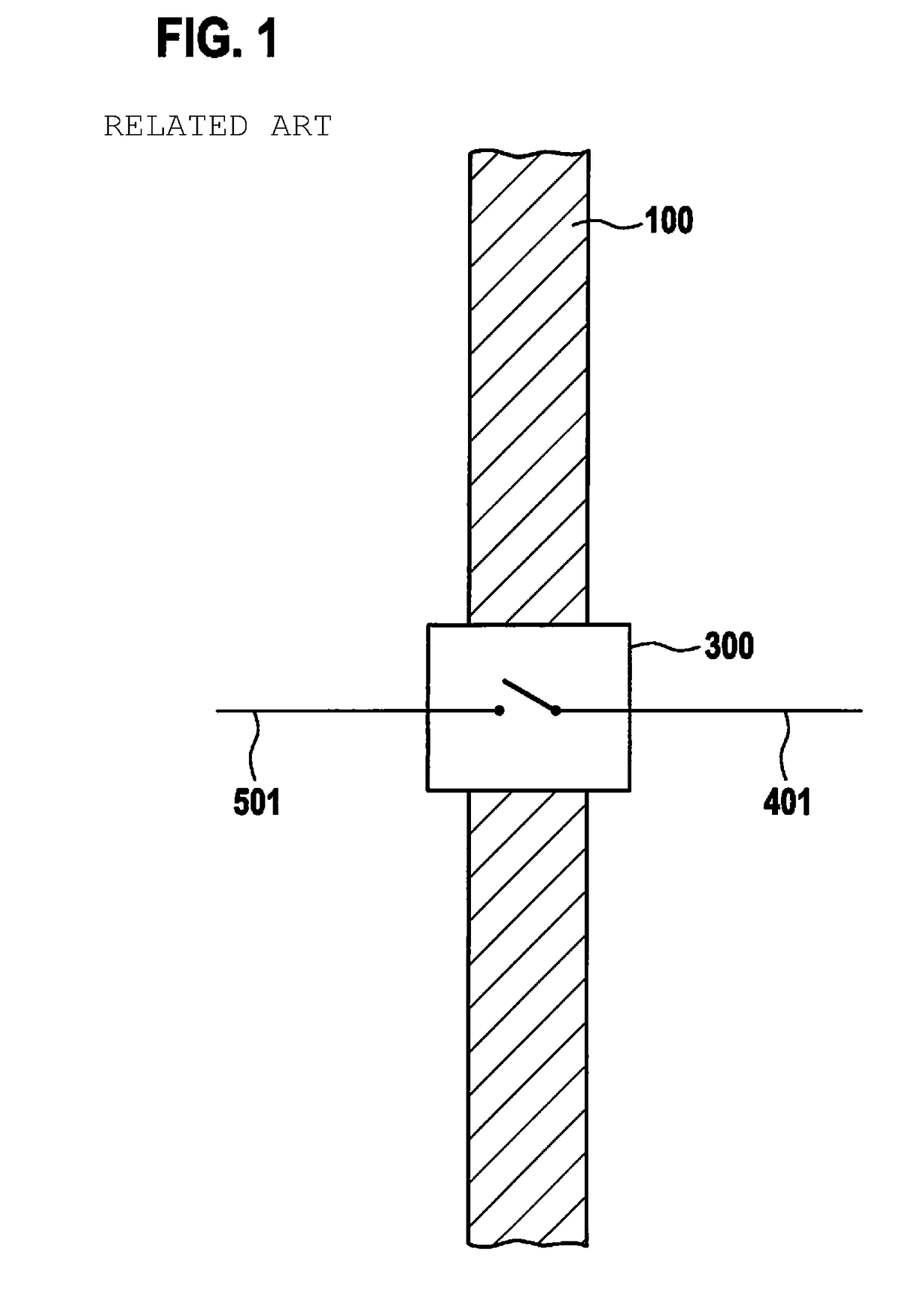
[0025]FIG. 1 shows, as existing art, a switch 300, embodied as a disconnecting switch, on electrical supply conductors or connector means 401, 501 of thermally insulated electrochemical units, switch 300 disconnecting electrical supply conductors or connector means 401, 501 in the region of the passage of supply conductors or connector means 401, 501 through thermal insulator 100, and, in addition to interrupting the electrical connection, also considerably reducing heat flows via the electrical supply conductor.

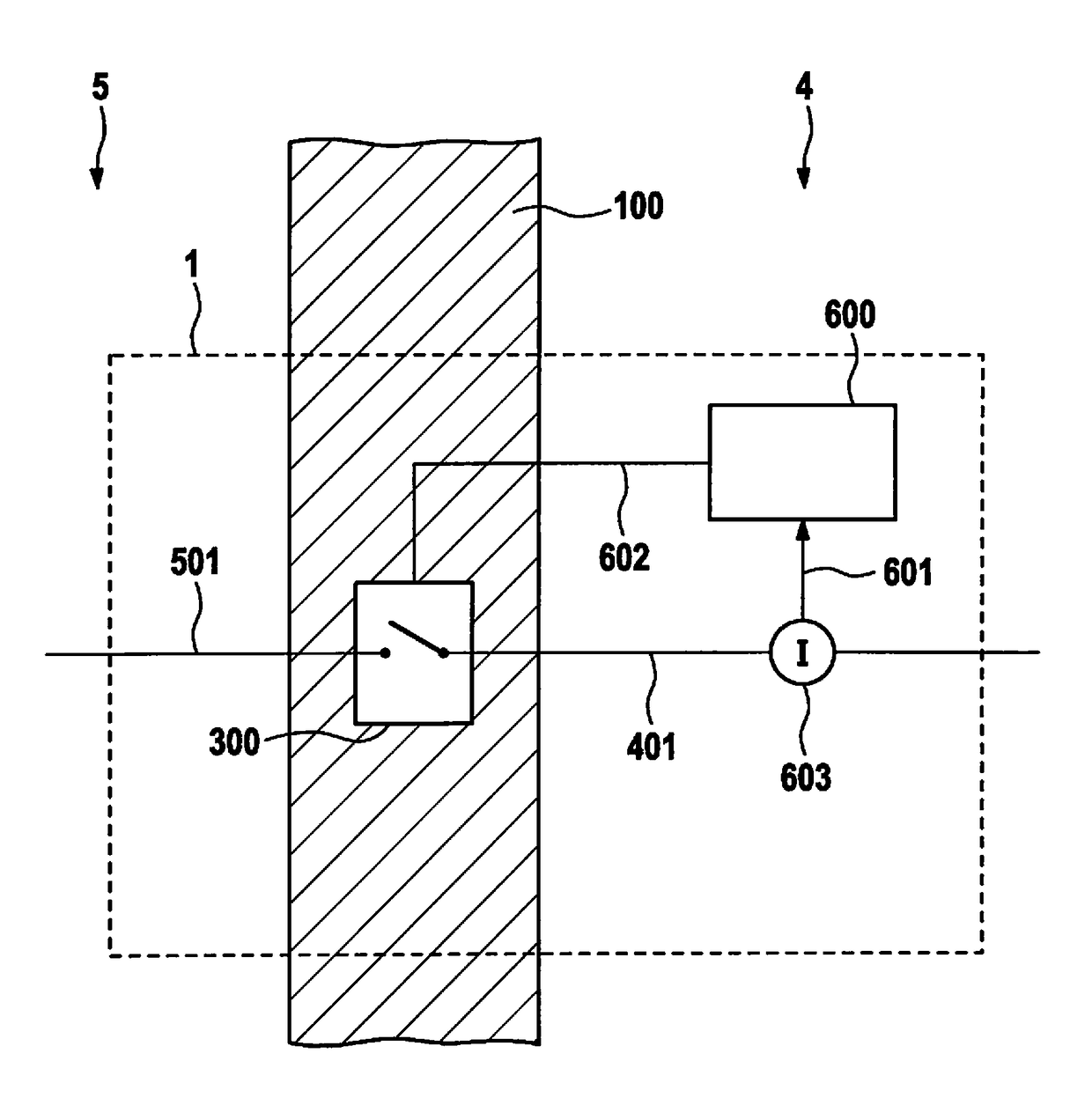
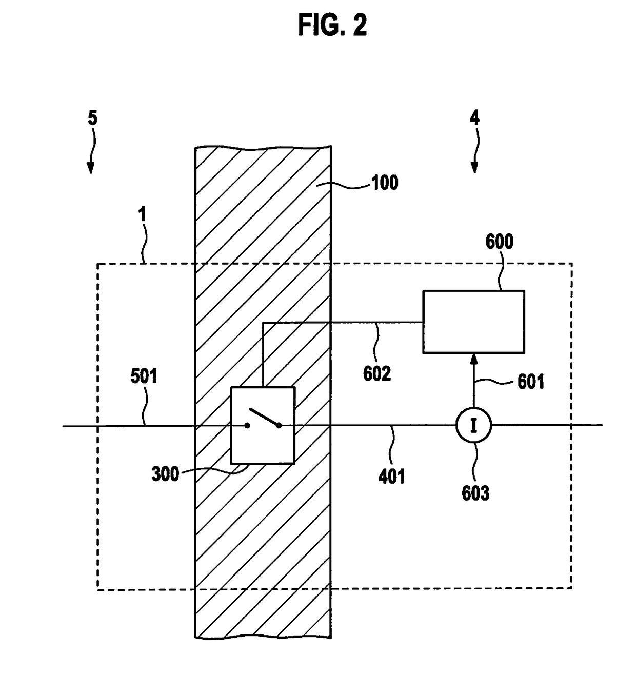
[0026]FIG. 2 shows a first exemplifying embodiment of an assemblage 1 according to the present invention having a thermally insulating switch 300 inside a thermal insulator 100, and having a control unit 600 for actuating switch 300. Assemblage 1 shown in FIG. 2 serves to constitute an electrical conductor passthrough through thermal insulator 100, as necessary, e.g., for electrical connection of a thermally insulated electrochemical battery to a load. Thermal insulator 100 ...


PUM


Abstract

An assemblage having a thermally insulating switch and a thermal insulator for constituting an electrical conductor passthrough through the thermal insulator. The thermal insulator insulates an inner space from an outer space, the assemblage having inner connector on the side of the inner space and outer connector on the side of the outer space, which are electrically conductively connectable by the switch. The assemblage has a control unit for controlling the thermally insulating switch, a current flowing through the switch is detectable by the control unit, the switch is controllable by the control unit in such a way that the switch is actuatable only in a substantially zero-current state, and the switch is disposed in the thermal insulator in such a way that thermal insulation between the inner connector and the outer connector is accomplished by way of the switch in the open state.

Description

FIELD[0001]The present invention relates to an assemblage having a thermally insulating switch and a thermal insulator for constituting an electrical conductor passthrough through the thermal insulator, in particular for electrical connection of a thermally insulated electrochemical battery to a load. The present invention further relates to a thermally insulated electrochemical battery and to a battery management system for controlling the thermally insulated battery, the thermally insulated battery having a thermally insulating switch for constituting a conductor passthrough through the thermal insulator.BACKGROUND INFORMATION[0002]Electrical leads having a low electrical resistance as a rule also exhibit low thermal resistance. When an electrical lead is passed through a thermal insulator, a thermally insulating substance having a low thermal conductivity is interrupted at least in single-point fashion by the electrical lead having a high thermal conductivity, so that a thermal b...

Claims


Application Information

Patent Timeline
IPC IPC(8): H01H9/54H01M50/574
CPCH01H9/54H01M10/658H01M50/574Y02E60/10
Inventor LETSCH, ANDREASTHIELEN, JOERGTENZER, MARTIN
Owner ROBERT BOSCH GMBH
Learn More