Electrical device heat dissipation structure

a technology of heat dissipation structure and electric device, which is applied in the direction of coupling device connection, electrical apparatus casing/cabinet/drawer, instruments, etc., can solve the problems of increasing the signal transmission requirements of an electrical connector, affecting the efficiency of the electrical device, and causing the failure of the whole electrical device, so as to avoid the failure of the chip due to high temperature and improve the efficiency of the working stability of the mating connector

Inactive Publication Date: 2018-01-11
LOTES
View PDF14 Cites 6 Cited by
  • Summary
  • Abstract
  • Description
  • Claims
  • Application Information

AI Technical Summary

Benefits of technology

[0027]Compared with the related art, certain embodiments of the present invention have the following beneficial advantages:
[0028]In this electrical device heat dissipation structure, because the air blowing device can blow cold air to the mating connector through the air outlet, the failure of the chip due to high temperature is avoided, the working stability of the mating connector is efficiently improved, and the reliability of the whole electrical device is enhanced.

Problems solved by technology

Currently, because functions of an electrical device are increasingly powerful, signal transmission requirements of an electrical connector are increasingly high.
However, the chip produces a large amount of heat during operation.
If the heat cannot be discharged in time, the chip would fail due to an excessively high temperature, which destroys the cable connector and causes the whole electrical device to fail.
Therefore, a heretofore unaddressed need exists in the art to address the aforementioned deficiencies and inadequacies.

Method used


Image

  • Electrical device heat dissipation structure
  • Electrical device heat dissipation structure
  • Electrical device heat dissipation structure

Examples


first embodiment

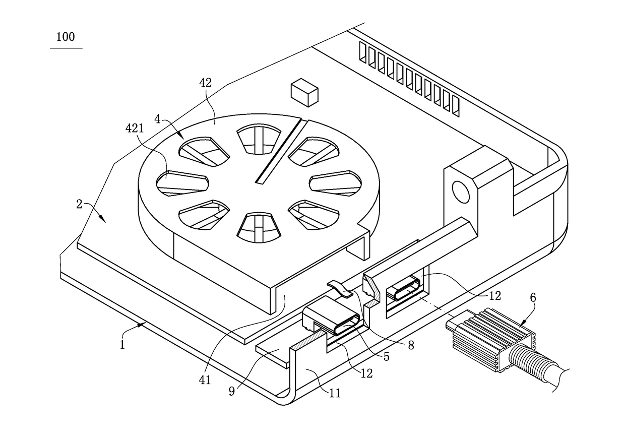
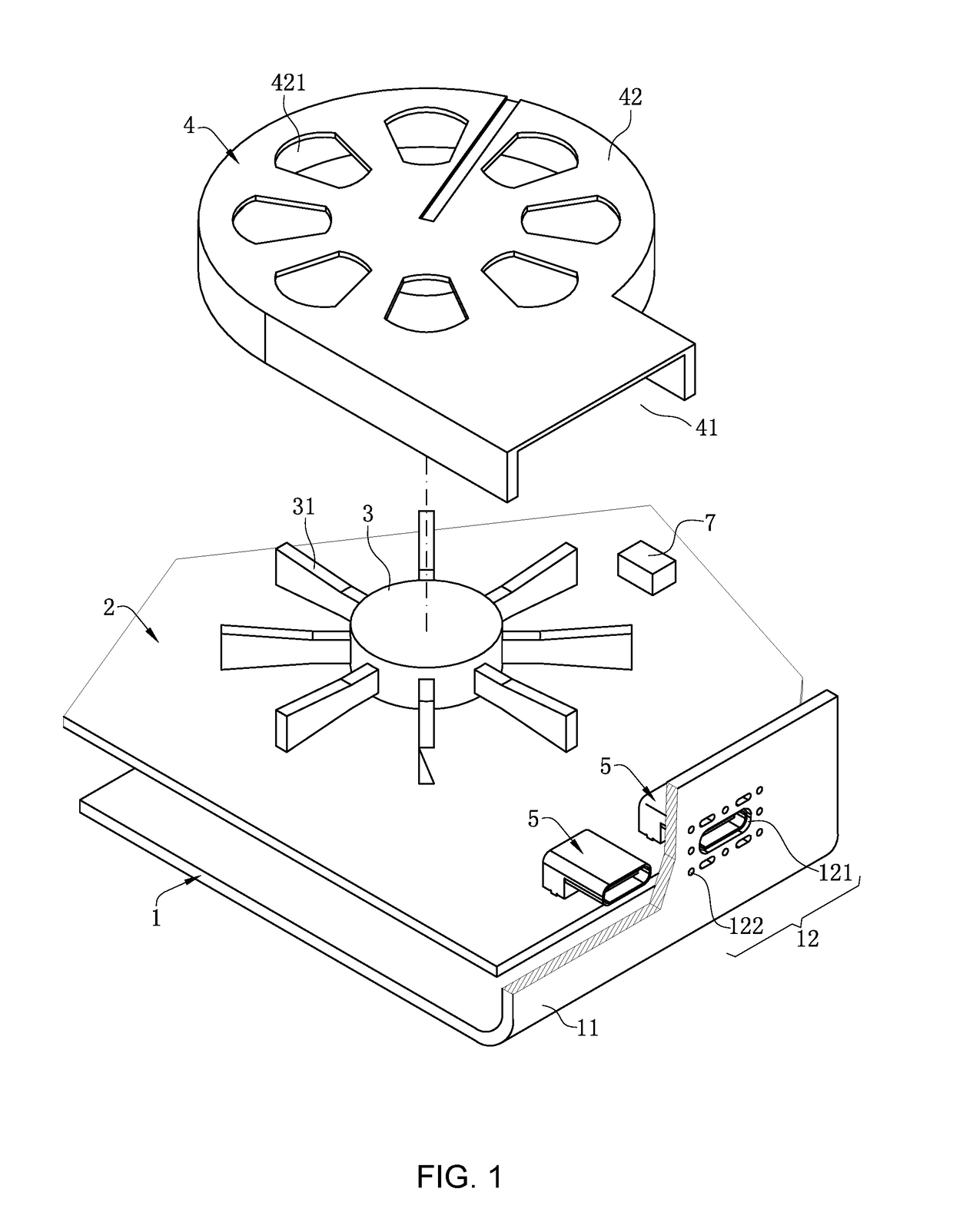
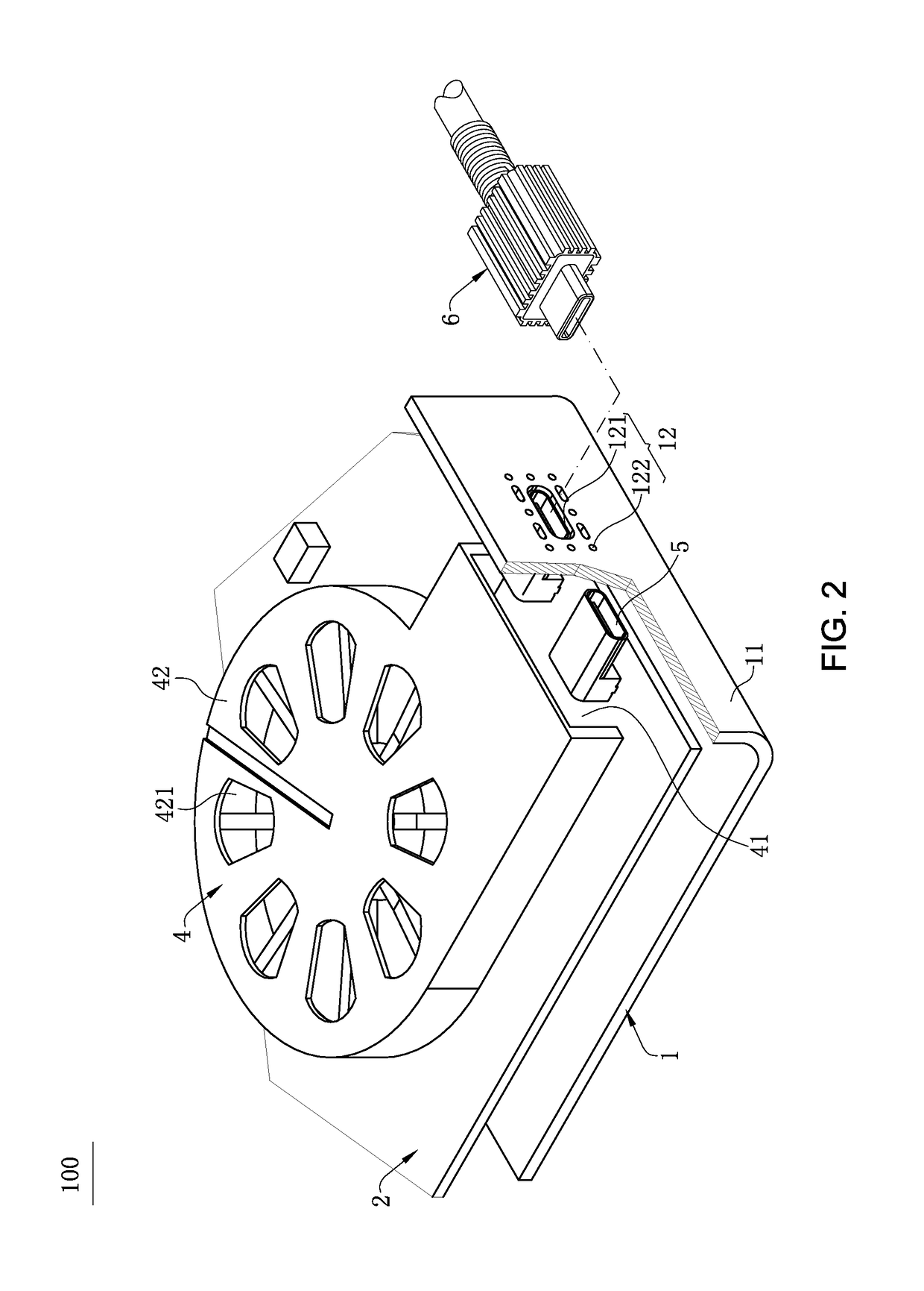
[0047]FIGS. 1-3 show the electrical device heat dissipation structure 100 of the present invention. The casing 1 has a sidewall 11. An opening 12 is disposed on the sidewall 11. Each opening 12 includes a insertion opening 121 and multiple air outlets 122 located around the insertion opening 121. The electrical connector 5 is exposed at the insertion opening 121, so that the mating connector 6 may be plug-connected to the electrical connector 5 through the insert opening 121. The air guide member 4 has an air blowing opening 41. The air blowing opening 41 directly faces the air outlet 122, such that the air blowing device 3 can blow air to the mating connector 6 through the air outlet 122, so as to lower the temperature of the mating connector 6. To make air blown by the air blowing device 3 cover a maximum range of the mating connector 6 and accelerate a heat dissipation rate of the mating connector 6, in the side wall, the air outlets 122 are provided relatively tilted to the inse...

second embodiment

[0049]FIGS. 7 and 8 show the present invention. The second embodiment 2 fundamentally differs from the first embodiment 1 in that in this embodiment, the central line of the air outlets 122 is parallel to the central line of the insertion opening 121. However, along a plug direction of the mating connector 6 and the electrical connector 5, and viewing toward the casing 1, the mating connector 6 shields halves of areas of the air outlets 122. In this way, it can be ensured that the mating connector 6 is located on a path of blowing air from the air outlets 122, so that air blown from the air outlets 122 blows over the outer metal shell 67. In other embodiments, the mating connector 6 only needs to shield at least a portion of the air outlets 122, so that air blown from the air outlets 122 blows over the outer metal shell 67. Thus the structures and the locations of the air outlets 122 and the mating connector 6 are not limited to the embodiments of the present invention.

[0050]As show...


PUM


Abstract

An electrical device heat dissipation structure includes an air blowing device, a casing, and a mating connector. The casing is disposed with at least one air outlet, an electrical connector and a power supply. The power supply provides power to the air blowing device. The mating connector has a chip. The mating connector is electrically connected with the electrical connector. The air blowing device is configured to blow air to the mating connector through the at least one air outlet, so as to improve dissipation of heat generated by the chip at work, and to reduce a temperature of the mating connector.

Description

CROSS-REFERENCE TO RELATED APPLICATION[0001]This non-provisional application claims priority to and benefit of, under 35 U.S.C. §119(a), Patent Application No. 201620719695.3 filed in P.R. China on Jul. 11, 2016, the entire content of which is hereby incorporated by reference.FIELD OF THE INVENTION[0002]The present invention relates to an electrical device heat dissipation structure, and more particularly to an electrical device heat dissipation structure that is capable of reducing a temperature of a cable connector.BACKGROUND OF THE INVENTION[0003]A common cable connector in the industry includes a circuit board, a connector electrically connected to one end of the circuit board, and a flexible flat cable electrically connected to the other end of the circuit board. Currently, because functions of an electrical device are increasingly powerful, signal transmission requirements of an electrical connector are increasingly high. To make a cable connector to have a greater data transm...

Claims


Application Information

Patent Timeline
Patent Type & Authority Applications(United States)
IPC IPC(8): H05K7/20H01R12/72H05K1/02H05K5/02H05K1/14H05K7/14H01R12/73
CPCH05K7/20154H05K7/20436H05K5/0247H05K7/1427H05K1/148H05K7/20145H05K2201/10325H01R12/722H01R12/721H01R12/73H05K7/20163H05K2201/10356H05K1/0203H05K5/0286G06F1/203H05K1/142H05K1/147
Inventor LIN, CHIN CHI
Owner LOTES
Why Eureka
Try Eureka