Real-time inspection of automated ribbon placement

Active Publication Date: 2018-01-18
NAT RES COUNCIL OF CANADA
View PDF1 Cites 11 Cited by
  • Summary
  • Abstract
  • Description
  • Claims
  • Application Information

AI Technical Summary

Benefits of technology

[0018]Applicant has surprisingly discovered that OCT profilometry produces enough useful topographical information, quickly enough during the manufacturing process, even at a range of incidence angles, for automated inspection of ribbon deposition and identification of defects. The profilometry has been demonstrated on CFRP surface, which is notoriously difficult because of its high absorption and the s

Problems solved by technology

The profilometry has been demonstrated on CFRP surface, which is notoriously difficult because

Method used


Image

  • Real-time inspection of automated ribbon placement
  • Real-time inspection of automated ribbon placement
  • Real-time inspection of automated ribbon placement

Examples


Example

EXAMPLE

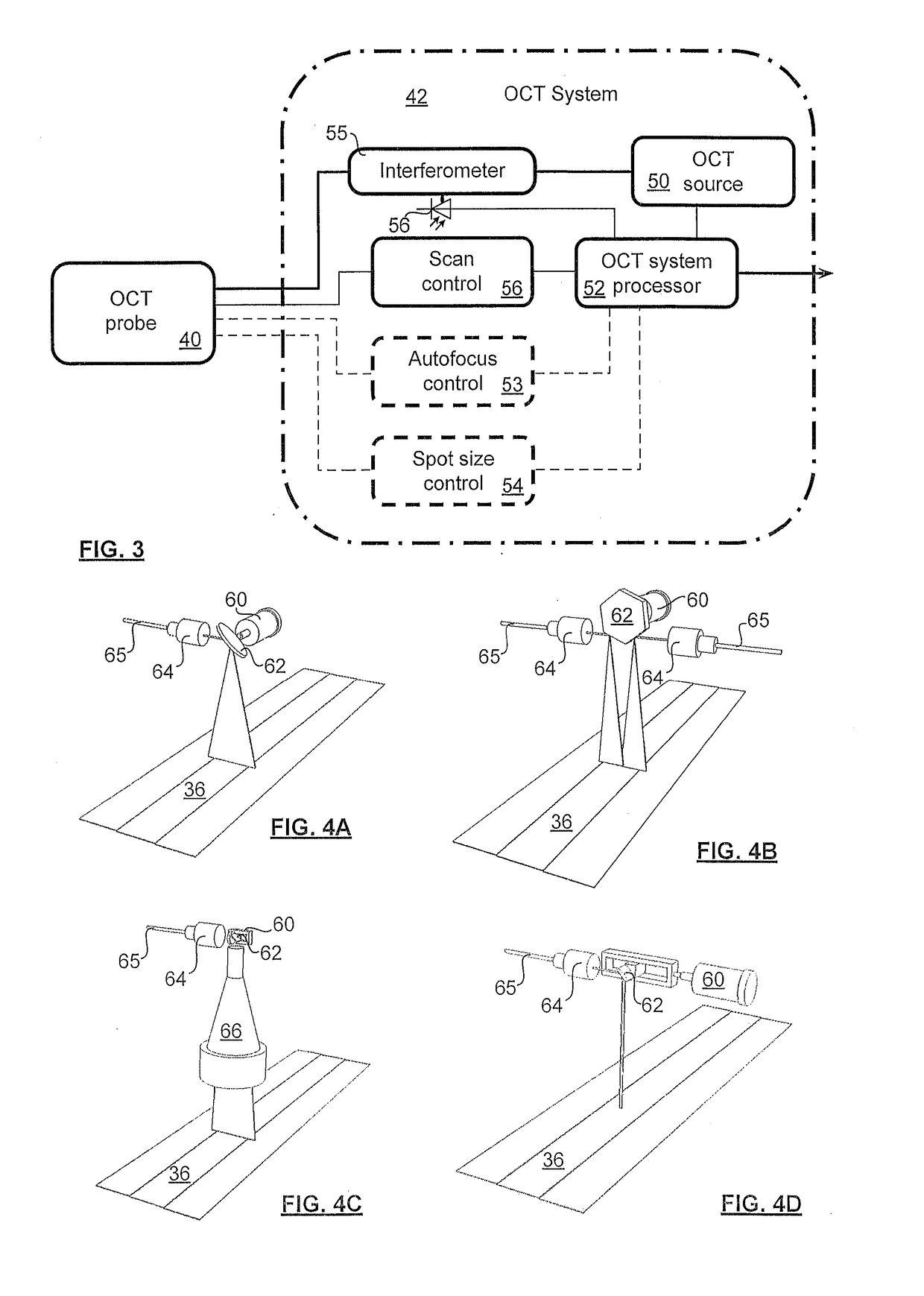
[0087]Applicant has tested an OCT system for use in profile characterization of a composite part formed of CFRP, is shown in FIG. 8. An optical scanner, as shown in FIG. 4A, but with a telecentric lens, was fixed to an AFP head (Automated Dynamics, model TPTSFPS-XP-FPS2.0-6AGMP-MVP). The transverse displacement of the focused optical beam on the surface was 23 mm, which corresponded to the ⅝th inch ribbon that had been deposited with 5⅛th inch tows. The scanner was fixed to the AFP head, and the scanning pattern was a continuous constant reciprocating motion so the probe beam followed a zigzag pattern over the sample.

[0088]Point measurements were made at a rate of 30,000 measurements per second. The deposition speed was 50 mm / s and the line scan rate was 26 Hz since only every other line scan was kept. The spacing between the lines was 1.92 mm. Each line scan was composed of 586 measurements. The lateral distance between successive measurement points was 0.039 mm.

[0089]The di...


PUM

PropertyMeasurementUnit
Speedaaaaaaaaaa
Radiusaaaaaaaaaa
Widthaaaaaaaaaa

Abstract

A technique for automated online inspection of manufacture of a fibre reinforced polymer composite part during automated ribbon placement (e.g. ATL or AFP) uses interferometric inspection (e.g. OCT) to detect deviations from a planned lay-up for the part, to identify defects. On line, real-time inspection (i.e. on-the-fly) is demonstrated, and edge type defects and whole surface defects are identifiable. A sensor is demonstrated that does not extend a working envelope of the robotic head used for rib bon placement.

Description

FIELD OF THE INVENTION[0001]The present invention relates in general to the automated inspection of automated ribbon placement, and in particular to on-line, real-time automated monitoring of deposition of ribbons of fibres (including prepreg tows, and slit or whole tapes), by a robotic ribbon placement machine, such as an automated tape layup or automated fibre placement machine.BACKGROUND OF THE INVENTION[0002]Polymer matrix composites (or Fibre Reinforced Polymers FRP) are commercially important materials because of their stiffness, strength, and lightness, because of a suite of design and manufacturing techniques that allow for engineering of optimal weight for a desired strength and stiffness at each point on a part, even if the part has a complex geometry, or a very large size. Parts having complex shapes and large structural parts, such as a fuselage or wing of an aircraft, rotors of helicopters, and airfoils for wind turbines, are formed of such composite materials.[0003]One...

Claims


Application Information

Patent Timeline
IPC IPC(8): G01N21/84B29C70/38G01B9/02B29C70/54B29K307/04G01B11/30
CPCG01N21/8422G01B9/02091B29C70/38B29C70/54G01N2021/8472G01B11/303B29K2307/04
Inventor MONCHALIN, JEAN-PIERREYOUSEFPOUR, ALILAMOUCHE, GUYGAUTHIER, BRUNOROY, STEVENPADIOLEAU, CHRISTIAN
Owner NAT RES COUNCIL OF CANADA
Why Eureka
Try Eureka