Lossless Snubber Circuits

Active Publication Date: 2018-01-18
APPULSE POWER INC
View PDF7 Cites 9 Cited by
  • Summary
  • Abstract
  • Description
  • Claims
  • Application Information

AI Technical Summary

Benefits of technology

[0009]The single-quadrant switch is connected in series with the energy storage element, while the voltage regulator is connected in parallel with the energy storage element. The voltage regulator output voltage rail is connected to a load provided in the form of a floating semiconductor switch gate driver, control circuit or similar device. In such a way, the embodiment provides an alternative path for the SMPS leakage inductance current to commute through the series single-quadrant switch and energy storage element. The embodiment also provides a method for the stored leakage energy to be recycled instead of dissipated, via the regulated output voltage rail of the voltage regulator. As a result, the semiconductor switch drain-to-source peak voltage is minimized during switching transients and the power losses of the voltage regulator and gate driver reduced.
[0010]In accordance with one aspect, there is pro

Problems solved by technology

As a result of the price sensitive nature of SMPS, the snubber circuits are typically limited to the cost-effective passive and power lossy resistor-capacitor-diode (RCD) configurations.
In systems sensitive to power losses and heat generation, the dissipation in lossy components i

Method used


Image

  • Lossless Snubber Circuits
  • Lossless Snubber Circuits
  • Lossless Snubber Circuits

Examples


Embodiment Construction

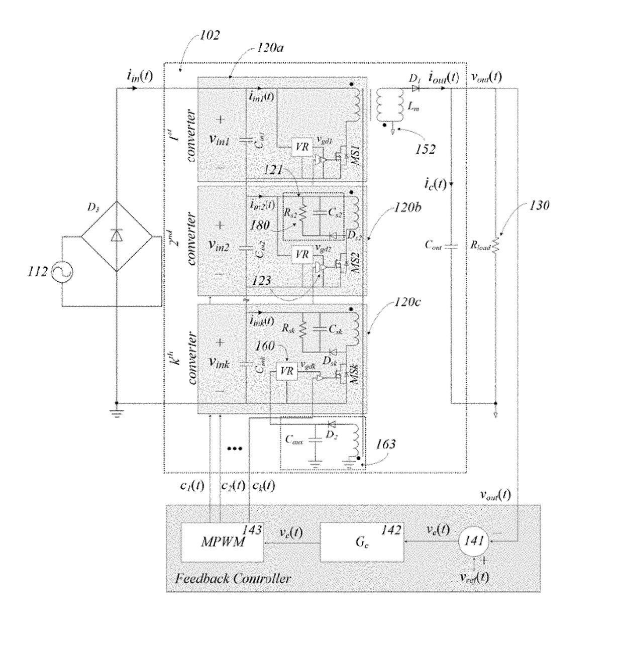
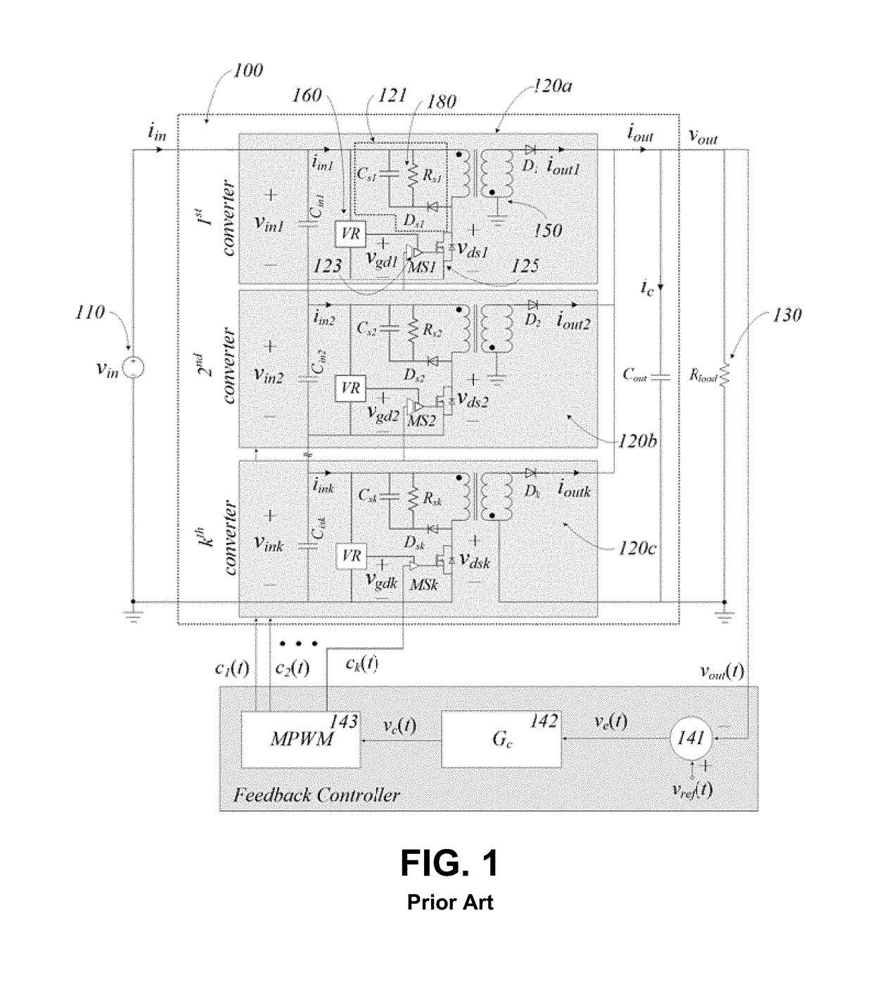
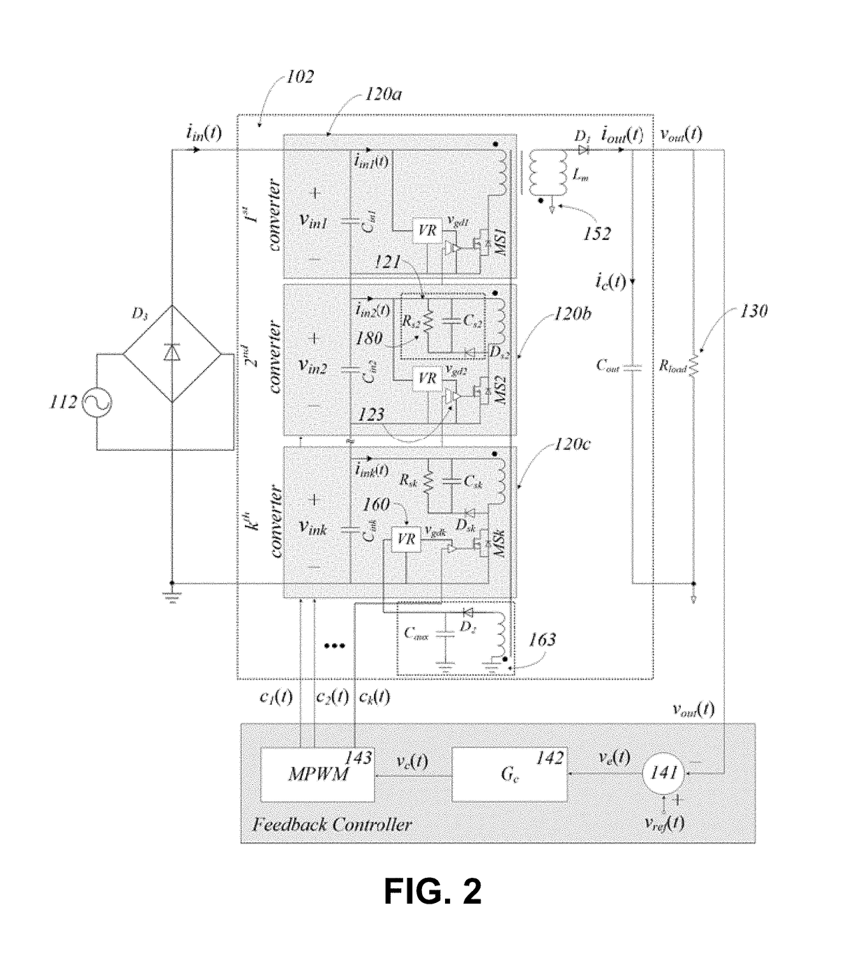
[0033]FIG. 1 shows an example of a stacked flyback converter 100, in accordance with the prior art. As depicted, the stacked flyback converter 100 has a direct current (DC) voltage source 110, with input voltage Vin, connected to the primary side of a string of serially connected flyback converter cells 120 (also known as 120a, 120b, and 120c). Each primary side flyback converter cell 120 comprises an RCD snubber 121 (having an energy storage device and a resistive element (e.g. resistor) pair 180), voltage regulator (VR) 160, gate driver (gd) 123, transformer 150 and semiconductor switch 125. The secondary side ports of the stacked flyback converter are, in turn, connected in parallel to an output load 130 providing an output voltage Vout. The output voltage is sensed and compared to a reference voltage Vref by a subtraction block 141. The voltage difference is then processed by a gain compensator 142, in order to calculate a control signal Vc. The control signal is passed to a mul...


PUM


Abstract

The combined voltage regulator and snubber circuit generally has a voltage regulator device in parallel with the energy storage element of the snubber circuit operatively connectable in series with a leakage inductance current path; the leakage inductance being part of a magnetic component utilized in a switch-mode power supply having an input voltage source, controllable semiconductor switches, freewheeling semiconductor switches, feedback controller, reactive energy storage components and a load; the voltage regulator generally providing constant or variable voltage to the gate driver of the controllable semiconductor and/or feedback controller; the snubber circuit generally recycling leakage inductance energy to the input capacitor of a neighbouring cell in a multi-cell stacked converter.

Description

FIELD OF THE INVENTION[0001]The present invention relates generally to the field of switch-mode power supplies, and more particularly to the field of voltage snubbers and auxiliary power supplies.BACKGROUND OF THE INVENTION[0002]Switch-mode power supplies (SMPS) are power management components in modern electronic devices. They provide, among other things, power efficient and galvanically isolated power to multiple loads. In order to achieve high power processing efficiency and / or galvanic isolation, conventionally one or more magnetically coupled elements, semiconductor switches and associated gate driver circuits are required.[0003]The magnetically coupled elements often suffer from non-trivial leakage inductance phenomena, which necessitate the need for affordable voltage snubber circuits in order to control the semiconductor switch peak drain-to-source voltages. As a result of the price sensitive nature of SMPS, the snubber circuits are typically limited to the cost-effective pa...

Claims


Application Information

Patent Timeline
IPC IPC(8): H02M3/335H02M1/34H02M1/08
CPCH02M3/33507H02M1/34H02M1/08H02M3/285H02M1/0074
Inventor RADIC, ALEKSANDARMAHDAVIKHAH-MEHRABAD, SEYED-BEHZAD
Owner APPULSE POWER INC
Why Eureka
Try Eureka