
Bone analyzing device

a bone analyzing and bone technology, applied in the field of bone analyzing equipment, can solve the problems of increasing the risk of fracture, not being able to easily penetrate the mineral components, so as to achieve accurate fracture risk, accurate fracture risk, and high reliability

Inactive Publication Date: 2018-01-25
SHIMADZU CORP
View PDF9 Cites 6 Cited by
  • Summary
  • Abstract
  • Description
  • Claims
  • Application Information

AI Technical Summary

Benefits of technology

The invention is about a bone analysis system that calculates a fracture risk evaluation value based on bone density and structural parameters. The system considers that bone density and structure are important in evaluating fracture risk and combines them to get a more accurate result. By evaluating fracture risk from both angles, the system helps to better understand and mitigate the risk of fractures.

Problems solved by technology

When the osteoporosis progresses, the risk of fracture increases.
There is a risk of fracture as an index for determining how fragile bones are.
This is because mineral components are easily imaged in that X-rays do not easily penetrate mineral components.
That is, the fracture risk indicating the strength of bones cannot be accurately measured without the fracture of bones.
However, the fracture test of bones cannot be performed in actual.
Based on this idea, the bones having the same structural parameters also have the same fracture risk.

Method used


Image

  • Bone analyzing device
  • Bone analyzing device
  • Bone analyzing device

Examples


first embodiment

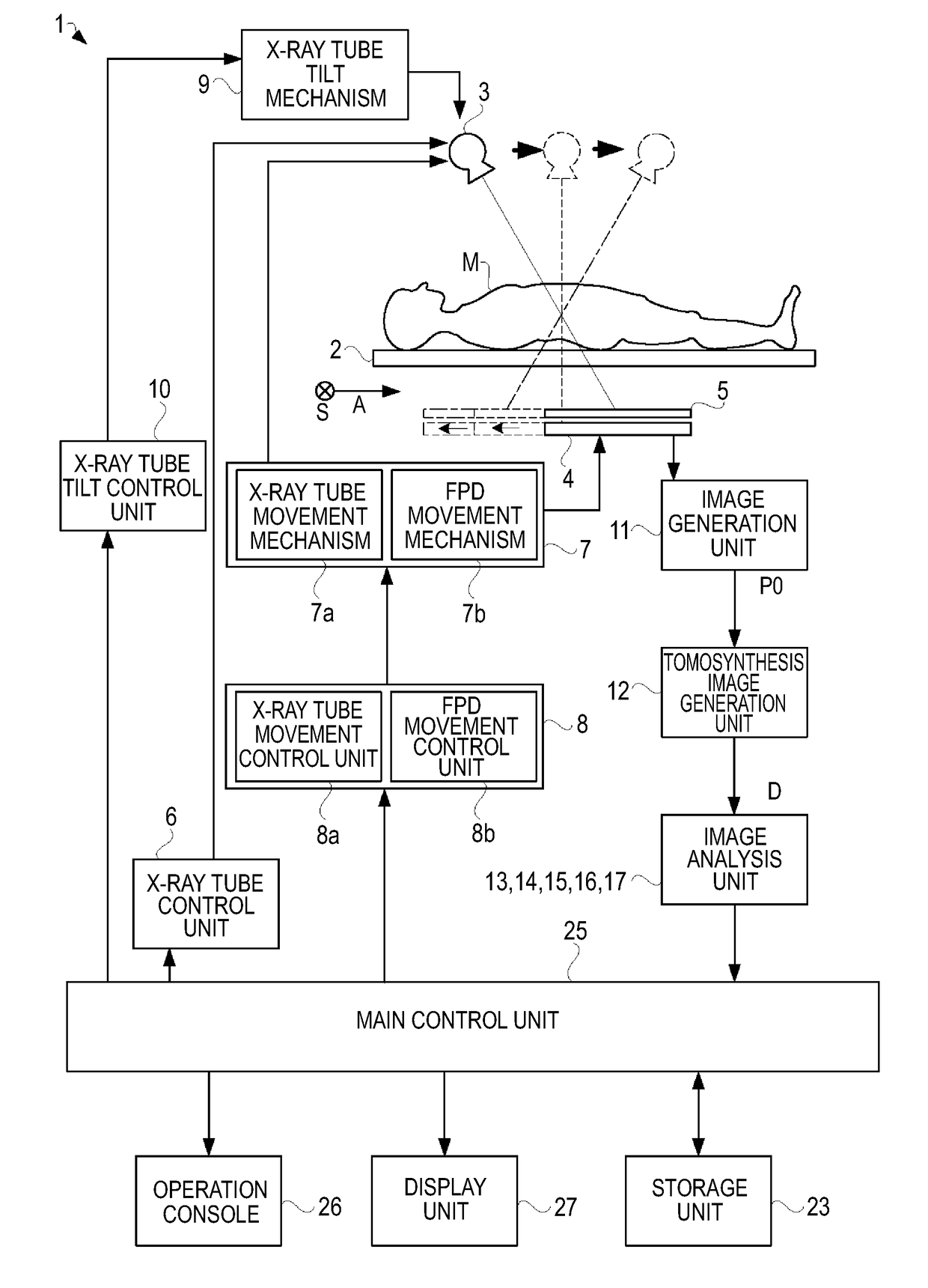
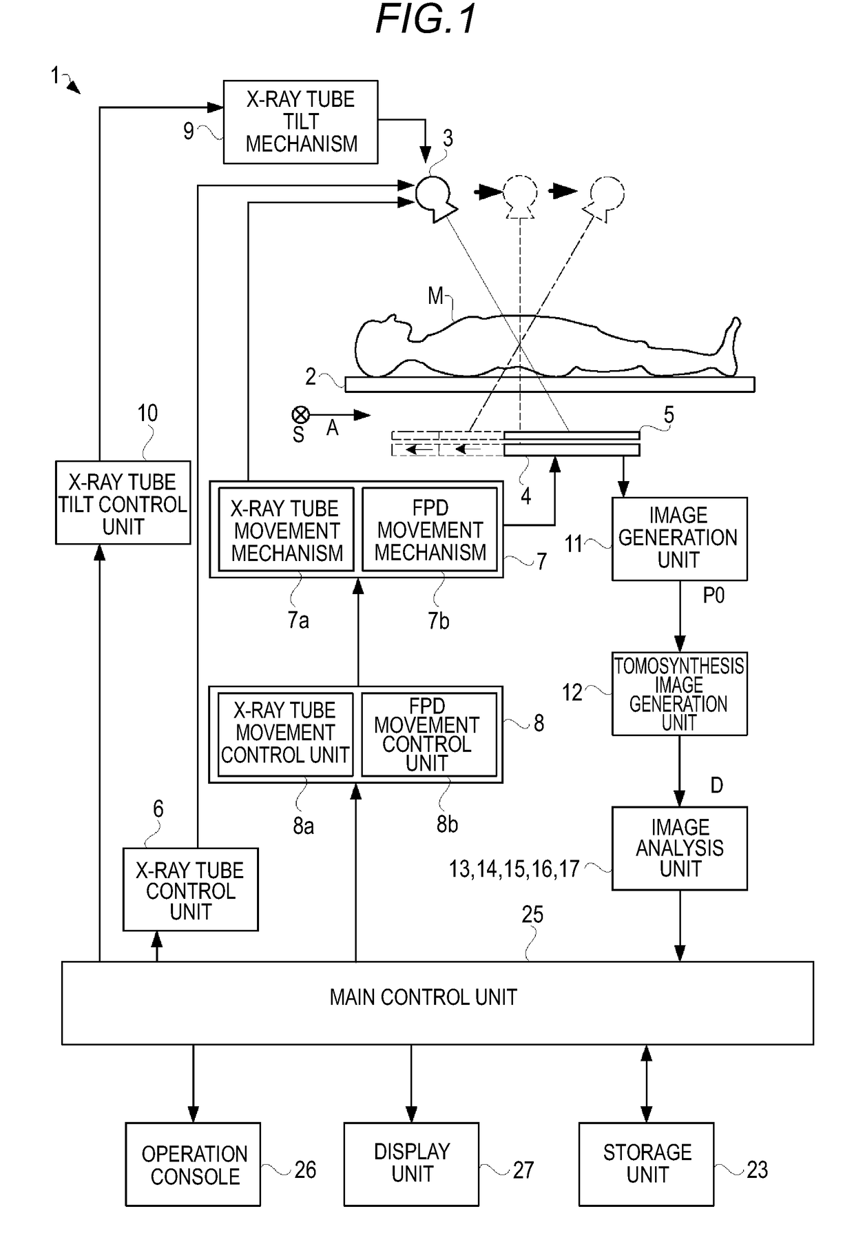
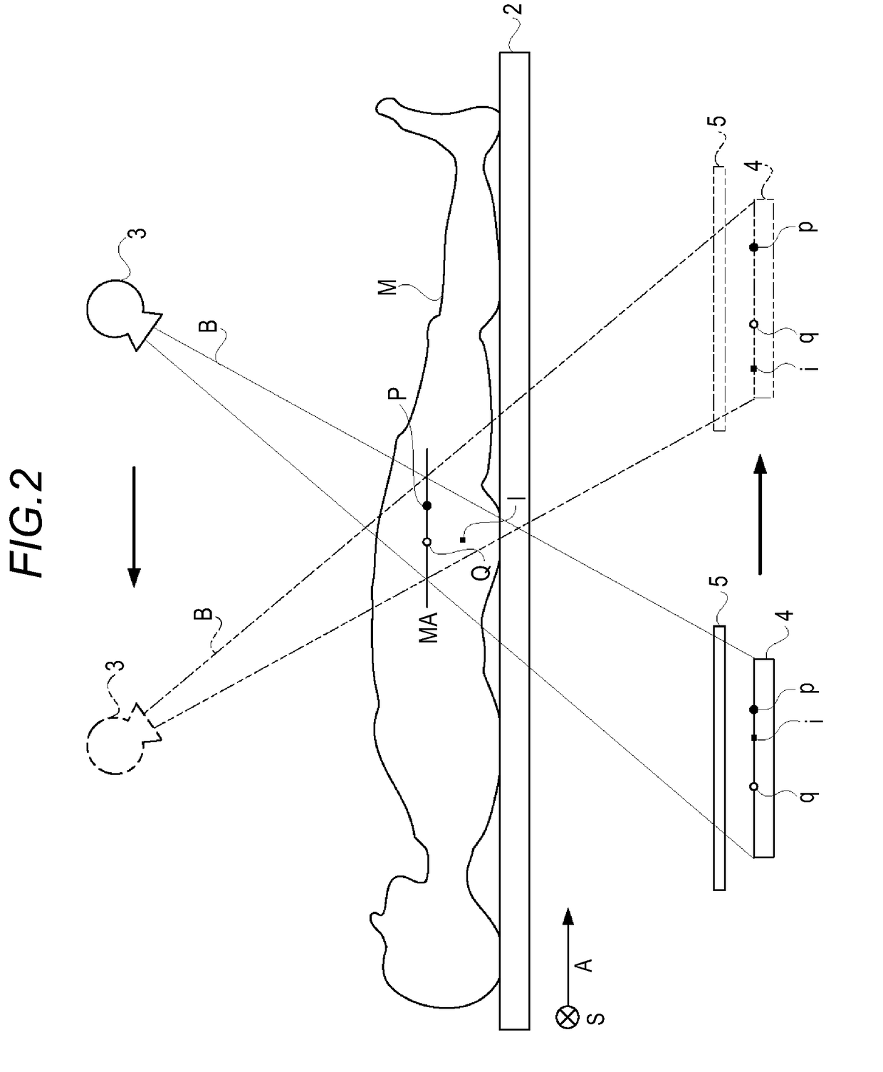
[0052]FIG. 1 is a functional block diagram showing a configuration of a bone analysis apparatus according to a first embodiment. As shown in FIG. 1, a bone analysis apparatus 1 according to the first embodiment includes a ceiling plate 2 which places a subject M corresponding to an X-ray tomography target thereon, an X-ray tube 3 which irradiates a cone-shaped X-ray beam to the subject M set on an upper portion (near one surface side of the ceiling plate 2) of the ceiling plate 2, an FPD 4 which is provided at a lower portion (near the other surface side of the ceiling plate) of the ceiling plate 2 and detects X-rays transmitted through the subject M, a synchronous movement mechanism 7 which synchronously moves the X-ray tube 3 and the FPD 4 in the opposite directions with an interested region of the subject M interposed therebetween while the center axis of the cone-shaped X-ray beam matches the center point of the FPD 4 at all times, asynchronous movement control unit 8 which cont...

second embodiment

[0121]Next, a bone analysis apparatus according to a second embodiment will be described. A configuration of the second embodiment is a configuration in which the X-ray tube 3 and the FPD 4 capture the tomographic image while moving in the body axis direction A of the subject M in a state of keeping a relative positional relation as shown in FIG. 16. That is, the synchronous movement mechanism 7 moves the FPD 4 toward one end of the ceiling plate 2 in the longitudinal direction in synchronization with the movement of the X-ray tube 3 toward one end of the ceiling plate 2 in the longitudinal direction.

[0122]A configuration of the X-ray imaging apparatus according to the second embodiment is similar to the functional block diagram of FIG. 1. The configuration of the second embodiment is different from that of the first embodiment in FIG. 1 in that the FPD 4 moves following the X-ray tube 3 (see FIG. 16) and the X-ray tube 3 is not inclined. Thus, in the second embodiment, the X-ray tu...


PUM


Abstract

A bone analysis apparatus capable of calculating a more highly reliable fracture risk evaluation value. A bone density of the invention is positioned for a partial description of a fracture risk. That is, in the invention, it is considered that an accurate fracture risk cannot be sufficiently obtained only by one of the bone density and a structural parameter although both the bone density and the structural parameter are important to know the fracture risk. According to the invention, the fracture risk is comprehensively evaluated on the basis of the structural parameter for evaluating a structure of a trabecular bone in addition to the bone density. With this configuration, since the fracture risk can be evaluated while also taking the structure of the trabecular bone into consideration, the fracture risk can be more accurately evaluated.

Description

TECHNICAL FIELD[0001]The present invention relates to a bone analysis apparatus which calculates a fracture risk evaluation value indicating a strength of a bone, and more particularly, to a bone analysis apparatus which calculates a fracture risk evaluation value on the basis of a bone density.BACKGROUND ART[0002]Osteoporosis is a disease in which a bone becomes fragile. When the osteoporosis progresses, the risk of fracture increases. In order to prevent the fracture caused by osteoporosis, it is effective to daily diagnose how fragile bones are and to take measures beforehand in consideration of the diagnosis result (for example, see Patent Document 1).[0003]There is a risk of fracture as an index for determining how fragile bones are. The fracture risk is an index showing how easily a fracture occurs and can be understood as an index showing how much bones can endure physical stress. In order to appropriately diagnose the bone state, this fracture risk needs to be calculated wit...

Claims


Application Information

Patent Timeline
IPC IPC(8): A61B6/00A61B6/02
CPCA61B6/505A61B6/025A61B6/54A61B6/5205A61B6/5217A61B6/461G16H50/30
Inventor YAMAMOTO, JUNYA
Owner SHIMADZU CORP
Learn More