
Mold, molding apparatus, and production method of bent glass

a production method and mold technology, applied in glass reforming apparatus, glass making apparatus, manufacturing tools, etc., can solve the problems of high cost of materials, easy contamination of molds, so as to achieve simple and easy production and increase productivity

Inactive Publication Date: 2018-01-25
ASAHI GLASS CO LTD
View PDF6 Cites 13 Cited by
  • Summary
  • Abstract
  • Description
  • Claims
  • Application Information

AI Technical Summary

Benefits of technology

The present invention aims to provide a mold, molding apparatus, and production method for glass molding that can prevent molding failure due to gas remaining between the body to be molded and the mold while ensuring that a glass having no molding defect can be simply and easily produced while raising the productivity. The mold is designed to allow for high permeability of gas in the space between the body to be molded and the mold, preventing any occurrence of molding failure while producing a molded body with no molding defect and having a curvature part.

Problems solved by technology

The mold material described in Patent Document 1 has high durability, but the material itself is expensive.
In addition, since the mold is composed of a high-strength material, the processability is low, giving rise to a problem that fabrication of a large mold is difficult.
However, when a glass is molded using this carbon mold, a mold-induced defect due to dust from the carbon material is readily occurred.
Furthermore, the carbon mold can be hardly applied to a step of performing the molding in an air atmosphere, because oxidation readily proceeds during the molding, and the molding needs to be performed in a vacuum or an inert gas atmosphere such as N2 gas.
Accordingly, the molding process or the molding apparatus becomes cumbersome, and it is disadvantageously difficult to enhance the productivity.

Method used


Image

  • Mold, molding apparatus, and production method of bent glass
  • Mold, molding apparatus, and production method of bent glass
  • Mold, molding apparatus, and production method of bent glass

Examples


first configuration example

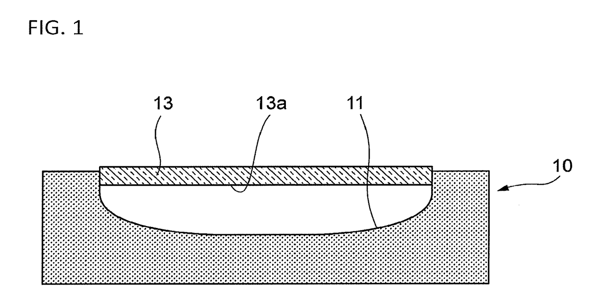
[0024]FIG. 1 shows a cross-sectional view of the mold of this embodiment.

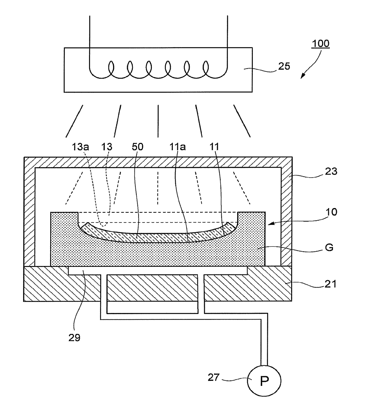
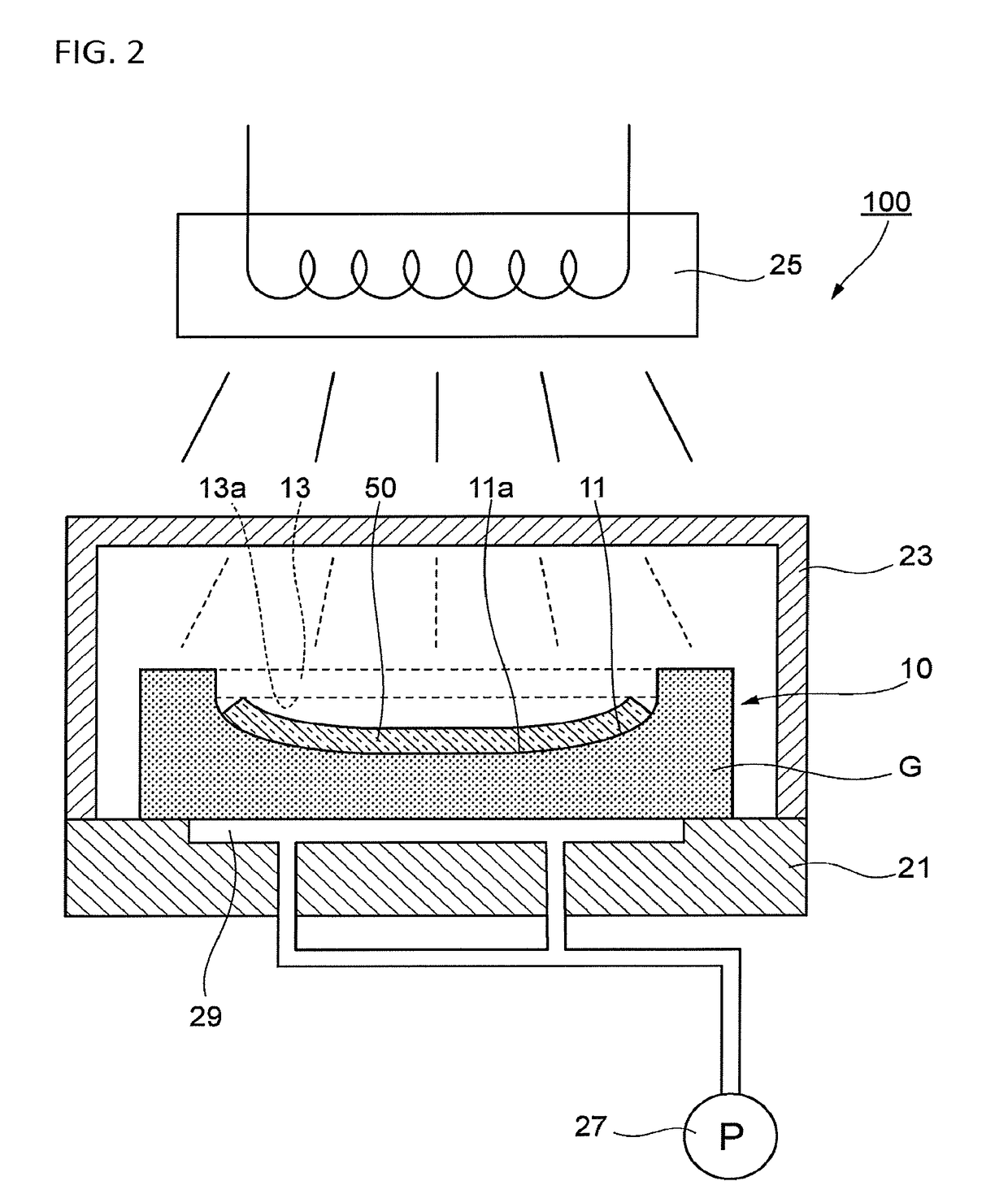
[0025]The mold 10 for molding a bent glass has a concave molding surface 11 on the top surface. The molding surface 11 has the same surface shape as the design shape of a bent glass having a curvature part.

[0026]A glass to be molded 13 as a body to be molded is placed on the mold 10, and the glass to be molded 13 is heated to a temperature not less than the softening point. The heated glass to be molded 13 deforms along the molding surface 11 due to softening by heating and the later-described exterior force such as gravity, suction power and pressing force, and a first main surface 13a abuts the molding surface 11 of the mold 10. The shape of the molding surface 11 is thereby transferred to the glass to be molded 13. The glass to be molded 13 is preferably heated such that the equilibrium viscosity becomes from 106.5 Pa·s to 1012.5 Pa·s. The equilibrium viscosity is more preferably from 107 Pa·s to 1010 Pa·s. ...

second configuration example

[0083]FIG. 4 is a cross-sectional view of a main part of a molding apparatus illustrating a second configuration example of the mold.

[0084]In the mold 10A of this configuration, a suction hole 17 extended from the molding surface 11 to the back surface on the opposite side of the molding surface 11 is formed. The opening 18 of the suction hole 17 open to the back surface of the mold is arranged to face the suction path 29, and a negative pressure from the suction path 29 is supplied to the suction hole 17.

[0085]In this mold 10A, the glass to be molded 13 is caused to follow the molding surface 11 by supplying a negative pressure to the suction path 29 and the suction hole 17 by a suction pump (not shown). In this case, a negative pressure is supplied from the suction path 29 to the molding surface 11 side through voids of the mold 10A and since a negative pressure is directly supplied to the molding surface 11 side also from the suction hole 17, the supply speed of the negative pres...

third configuration example

[0087]FIG. 5 is a cross-sectional view of a main part of a molding apparatus illustrating a third configuration example of the mold.

[0088]The mold 10B of this configuration molds a bent glass 50 by a gravity molding process.

[0089]In the gravity molding process, a glass to be molded 13 is placed on the mold 10, and the glass to be molded 13 is heated, softened and deformed downward by its own weight. As a result, the first main surface 13a of the glass to be molded 13 is brought into contact with the molding surface 11, and the shape of the molding surface 11 is transferred to the glass to be molded 13.

[0090]In the mold 10B of this configuration, a negative pressure need not to be supplied, and installation of a suction pump or a suction channel is unnecessary. In addition, the negative pressure supplied, the timing of supply, etc. need not be controlled, and the configuration of the molding apparatus and the control for molding can be simplified. As for actions and effects of this c...


PUM

PropertyMeasurementUnit
porosityaaaaaaaaaa
porosityaaaaaaaaaa
arithmetic average roughnessaaaaaaaaaa

Abstract

A mold has a molding surface for hot molding of a body to be molded. The mold includes a glass having a porosity of 0.01% or more and containing 95 mol % or more of SiO2. A molding apparatus includes the mold. A method for producing a bent glass includes a placing step and a molding step. In the placing step, a glass to be molded is placed on a mold including a glass having a porosity of 0.01% or more. In the molding step, the glass to be molded which has been placed on the mold is heated, and then, the glass is caused to be molded to follow a molding surface of the mold.

Description

CROSS-REFERENCE TO RELATED APPLICATIONS[0001]This application claims priority from Japanese Patent Application No. 2016-144762 filed on Jul. 22, 2016, the entire subject matter of which is incorporated herein by reference.BACKGROUND OF THE INVENTIONTechnical Field[0002]The present invention relates to a mold, a molding apparatus, and a production method of a bent glass.Background Art[0003]For example, some of bent glasses at least partially having a curvature part, such as cover glass for in-vehicle displays, is produced through a molding step of heating a sheet glass placed on a mold to a temperature not less than the softening point and changing the shape to follow a molding surface of the mold.[0004]Patent Document 1 discloses a method in which a sheet glass is placed on a mold formed of silicon carbide or other materials, followed by heating by a radiation heater and molding to provide a desired surface shape. In addition, Patent Document 2 describes that a mold is produced by u...

Claims


Application Information

Patent Timeline
Patent Type & Authority Applications(United States)
IPC IPC(8): C03B23/035C03B23/025C03C21/00
CPCC03B23/0357C03B2215/05C03B23/025C03C21/002C03B23/0252C03B23/0302C03C3/06Y02P40/57
Inventor FUKUSHI, TAKANORIKANASUGI, SATOSHIFUJII, MAKOTOHORI, JUNJI
Owner ASAHI GLASS CO LTD
Learn More