Radiofrequency balloon catheter system

a radiofrequency balloon and catheter technology, applied in balloon catheters, medical science, surgery, etc., can solve problems such as restenosis, achieve the effects of reducing facilitating the passage through a stenosis and dilatation of the stenosis, and increasing the discharge rate of in-balloon solution

Inactive Publication Date: 2018-02-08
JAPAN ELECTEL
View PDF3 Cites 2 Cited by
  • Summary
  • Abstract
  • Description
  • Claims
  • Application Information

AI Technical Summary

Benefits of technology

[0026]Referring to FIG. 1A showing a schematic diagram of the present invention in accordance with the first aspect of the invention, when the solution within the balloon is suctioned via the catheter shaft, the check valve defined by the anterior neck and the inner tube is closed, thereby turning the pressure inside the balloon to negative, as shown in FIG. 1B. When the solution within the balloon is further suctioned, the balloon is deflated and then inserted into the stenosis site, as shown in FIG. 2. When a coolant is injected into the inside of the balloon, the balloon is inflated to open the check valve, thereby discharging the coolant to the outside of the balloon, thus cooling the balloon, as shown in FIG. 3. Discharge rate of the coolant depends on injection rate of the coolant to be injected into the balloon, and further on the elasticity and / or shape of the anterior neck of the balloon serving as a valving element. Further, an “overlap” between the anterior neck of the balloon, in communication with the outer tube, and the inner tube define a check valve that allows adjustment of the discharge rate by sliding the inner tube against the outer tube to change the extent of the “overlap”, as shown in FIGS. 1C and 1D. Concurrently therewith, upon delivery of radiofrequency current, a radio frequency electric field is radiated uniformly from the electrode for delivery of radiofrequency current arranged inside the balloon, thereby allowing the balloon to dilate the stenosis site by increasing an in-balloon pressure while heating the site. In the meantime, cooling of the balloon protects intima against heating, as illustrated in FIG. 4.
[0027]According to the first aspect of the invention, there can be provided a radiofrequency balloon catheter system enabling a balloon catheter thereof to easily pass through a stenosis and dilate the stenosis while heating the same, with an intima being protected against damage.
[0028]According to the second aspect of the invention, when the inner tube slides forward against the anterior neck of the balloon, the clearance gap between the inner tube and the anterior neck of the balloon become narrower to thereby decrease the discharge rate of the in-balloon solution. Meanwhile, when the inner tube slides backward against the anterior neck of the balloon, the clearance gap between the inner tube and the anterior neck of the balloon become wider to thereby increase the discharge rate of the in-balloon solution, as illustrated in FIGS. 5A and 5B.
[0029]According to the third aspect of the invention, when the inner tube slides backward against the anterior neck of the balloon, the clearance gap between the inner tube and the anterior neck of the balloon become narrower to thereby decrease the discharge rate of the in-balloon solution. Meanwhile, when the inner tube slides forward against the anterior neck of the balloon, the clearance gap between the inner tube and the anterior neck of the balloon become wider to thereby increase the discharge rate of the in-balloon solution, as illustrated in FIGS. 6A and 6B.
[0030]According to the fourth aspect of the invention, when the small holes in the inner tube slide backward to a position posterior to the anterior neck of the balloon, the small holes become cleared of the anterior neck to thereby increase the discharge rate of the in-balloon solution. Meanwhile, when the small holes in the inner tube slide forward to be faced against the anterior neck of the balloon, the small holes become covered by the anterior neck to thereby decrease the discharge rate of the in-balloon solution, as illustrated in FIG. 7.
[0031]According to the fifth aspect of the invention, the anterior neck of the balloon may has slits or otherwise perforated with small holes for letting the in-balloon solution be easily passed through the clearance gap between the inner tube and the anterior neck, thereby enhancing cooling capacity thereof, as illustrated in FIG. 8.

Problems solved by technology

The method, however, has a problem that restenosis may occur due to intimal proliferation caused by intimal ablation.

Method used


Image

  • Radiofrequency balloon catheter system
  • Radiofrequency balloon catheter system
  • Radiofrequency balloon catheter system

Examples


Embodiment Construction

[0049]As follows is a detailed description of embodiments of a radiofrequency balloon catheter system proposed by the present invention with reference to the appended drawings.

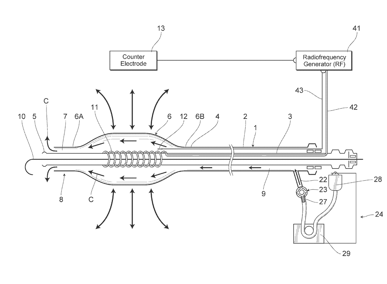
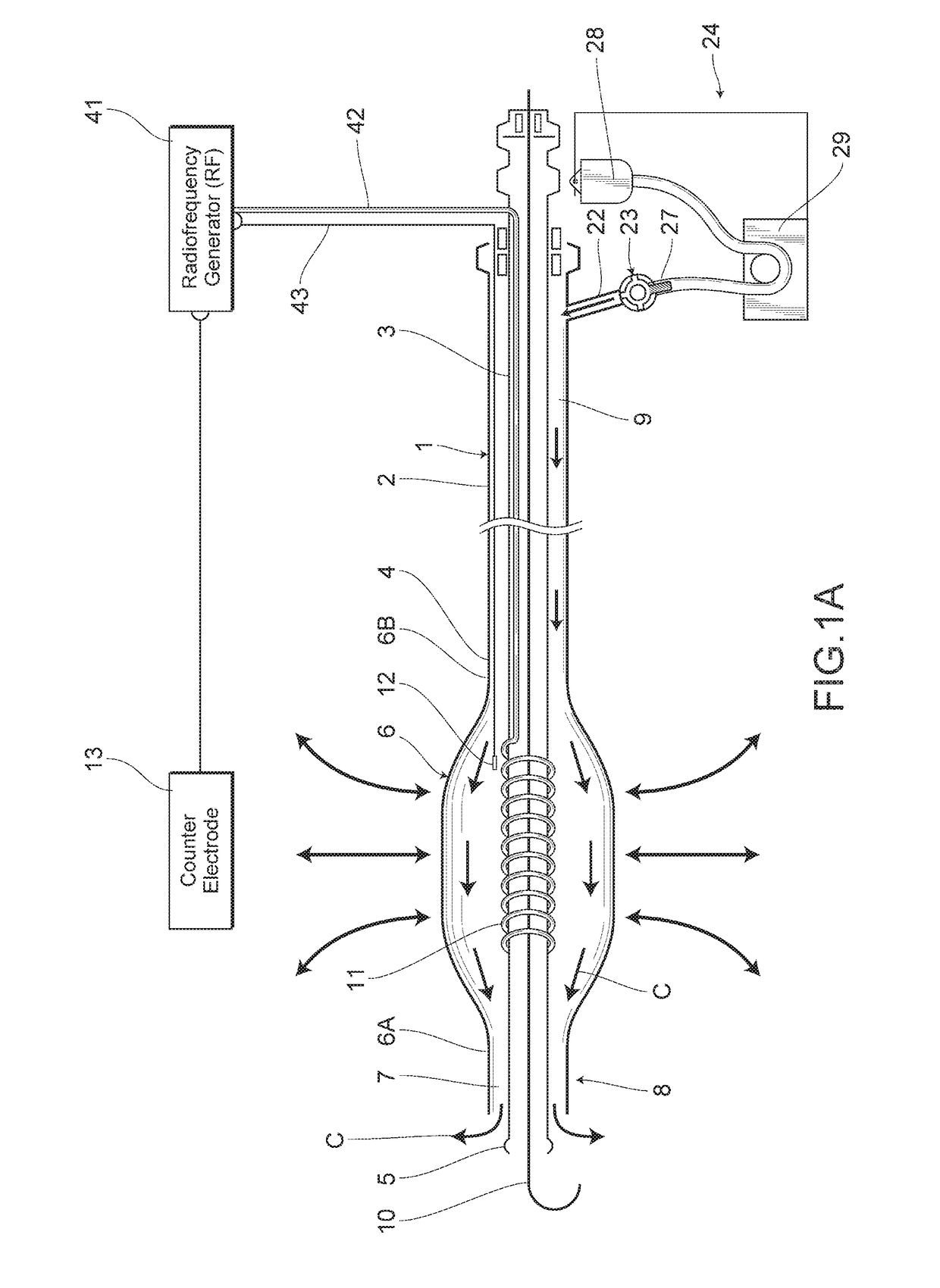
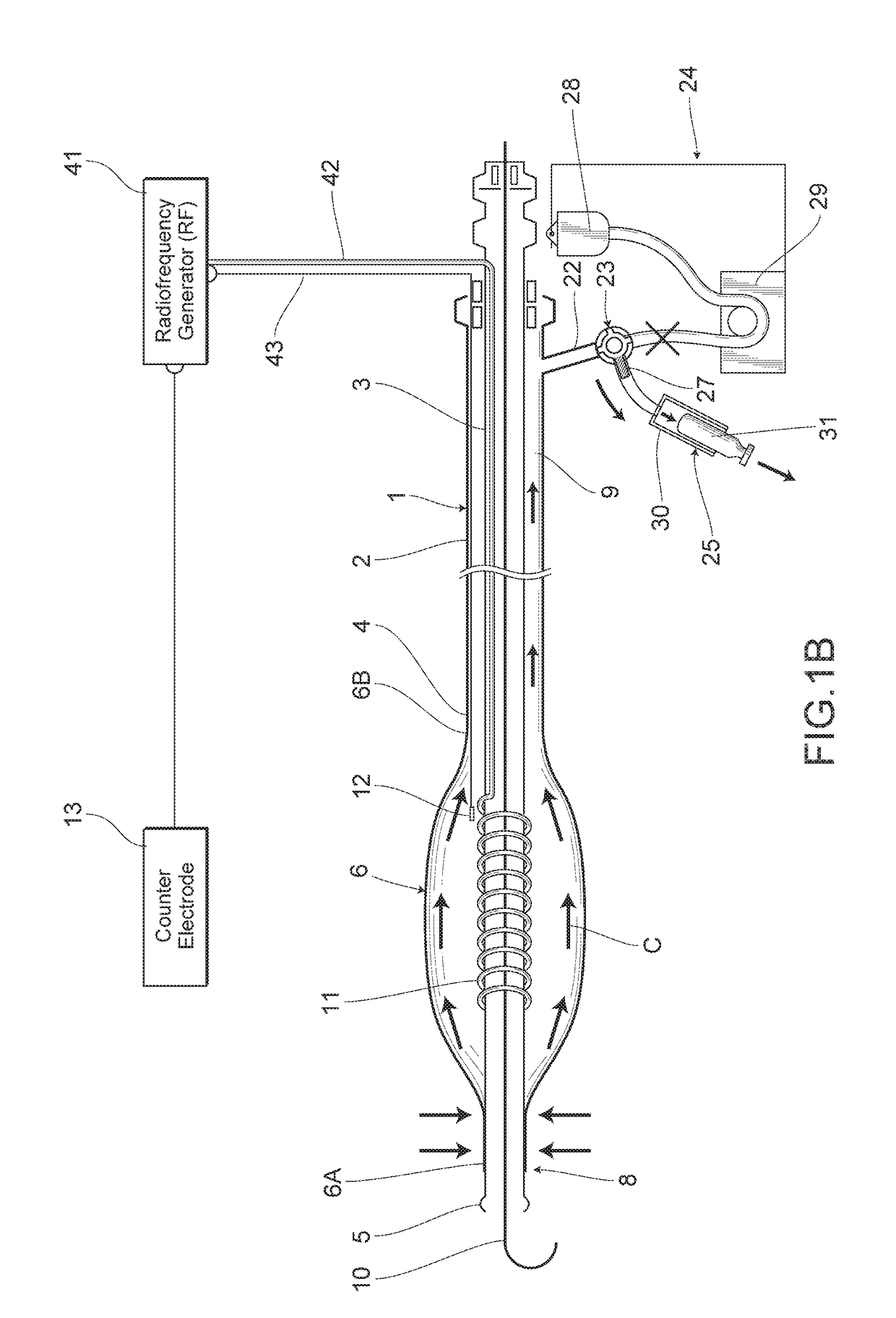
[0050]FIGS. 1A to 1B illustrate a major part structure of the radiofrequency balloon catheter system according to an embodiment of the present invention. In the drawings, numerical symbol 1 denotes a cylindrical catheter shaft that is rich in elasticity and insertable into a luminal organ. The catheter shaft 1 includes an outer tube shaft 2 and an inner tube shaft 3 which are hollow and slidable with each other in a longitudinal direction. A deflatable and inflatable balloon 6 is provided between a distal end 4 of the outer tube shaft 2 and a vicinity of a distal end 5 of the inner tube shaft 3. The balloon 6 is made of a thin membrane, which is formed of a heat-resistant resin such as polyurethane, PET (polyethylene terephthalate) or the like. The balloon 6 has an appropriate elasticity, and contains necks 6A...


PUM


Abstract

Provided is a radiofrequency balloon catheter system that allows inflation/deflation of the balloon in a controlled manner to enable the same to easily pass through the stenosis site without significantly changing the profile of a balloon (6). When a coolant is injected into the inside of the balloon (6), the balloon is inflated while discharging the coolant to the outside of the balloon (6), thus cooling the balloon (6) while applying a pressure to the balloon (6), with an intima being protected by perfusing the inside of the balloon (6) with a coolant. The radiofrequency balloon catheter system comprises a catheter shaft (1) comprising an inner tube shaft (3) and an outer tube shaft (2) that are slidable with each other; and a resilient balloon (6) that is inflatable and deflatable and provided between distal ends (4) of the inner tube shaft (3) and the outer tube shaft (2), said balloon (6) covering the inner tube shaft (3). The balloon (6) and the inner tube shaft (3) are in close proximity with each other to define a check valve (8). When the solution within the balloon (6) is suctioned to turn the pressure inside the balloon (6) to negative, the check valve (8) is closed and then the balloon (6) is deflated. Also, when a coolant is injected thereinto, the balloon (6) is inflated to open the check valve (8), thereby discharging the coolant to the outside. The radiofrequency balloon catheter system further includes an electrode for delivery of radiofrequency current (11) connected to a radiofrequency generator via a connecting wire (42) within said catheter shaft (1); and a solution transport path being in constant communication with an inside of the balloon (6) and connected to a liquid feed pump (29) for feeding a coolant (C).

Description

CROSS REFERENCE TO RELATED PATENT APPLICATIONS[0001]This application is a U.S. National phase application under 35 U.S.C. 371 of International Patent Application No. PCT / JP2015 / 062989, filed Apr. 30, 2015. The International Application was published in Japanese on Nov. 3, 2016 as International Publication No. WO / 2016174770 under PCT Article 21 (2).FIELD OF THE INVENTION[0002]The present invention relates to a radiofrequency balloon catheter system for thermally dilating a stenosis by inserting a deflated balloon into the stenosis within a hollow organ, and irradiating the stenosis with a radiofrequency electric field power via an internal electrode while applying a pressure to the balloon, with an intima being protected by perfusing the inside of the balloon with a coolant.BACKGROUND OF THE INVENTION[0003]Many of stenoses, such as coronary artery stenosis that cause angina or myocardial infarction are known to be due to arteriosclerotic lesions in a vascular membrane, and hence such...

Claims


Application Information

Patent Timeline
Patent Type & Authority Applications(United States)
IPC IPC(8): A61B18/14A61M25/10
CPCA61B18/1492A61M25/1018A61M25/104A61M25/1002A61B2018/0022A61B2018/00422A61B2018/00791A61B2018/00023A61B2018/00714A61B2018/1435A61B2018/1472
Inventor SATAKE, SHUTARO
Owner JAPAN ELECTEL
Why Eureka
Try Eureka