System for quickly detecting tunnel deformation

a tunnel structure and tunnel technology, applied in the field of civil engineering, can solve the problems of invertible negative effects, low measurement efficiency, and the inability to meet the needs of total-station instrument methods,

Active Publication Date: 2018-02-08
TONGJI UNIV
View PDF6 Cites 16 Cited by
  • Summary
  • Abstract
  • Description
  • Claims
  • Application Information

AI Technical Summary

Benefits of technology

[0006]The objective of the disclosure is to provide a system for quickly detecting tunnel deformation to overcome the defects of the existing devices in the prior art, to effectively solve the problem of mutual interference of testing data of cross section deformation and the problem of unstable test data caused by movements.

Problems solved by technology

When in use, cross sectional deformation in subway tunnels is an inevitable hazard and this hazard can cause invertible negative effects to the tunnel safety over time.
With only 2 hour intervals between subway operations each day, the measurement efficiency is extremely low.
The total-station instrument method can only meet the needs of detecting the cross section deformation of short-distance projects, and fails to cope with long-distance projects.
Such method cannot meet the demands of ensuring the operational safety of the future subway network.
But since the resulting files have a vast capacity and cannot give geometric parameters of cross section deformation, manual reading and judging are needed.
However, the geometric parameters of each annular cross section deformation obtained by the device are individual, independent and relative, failing to form a correlated coordinate system.
Generally speaking, testing equipment are not only very expensive, but also have incomplete functions and low cost-performance.

Method used


Image

  • System for quickly detecting tunnel deformation
  • System for quickly detecting tunnel deformation
  • System for quickly detecting tunnel deformation

Examples


Embodiment Construction

[0037]The present invention is described in detail with reference to the attached drawings and embodiment. The embodiment, implemented on the premise of the technical solution of the present invention, provides the detailed implementation means and the specific operating process on the basis of this technical solution, but the protective scope of the present invention is not limited to the following embodiment.

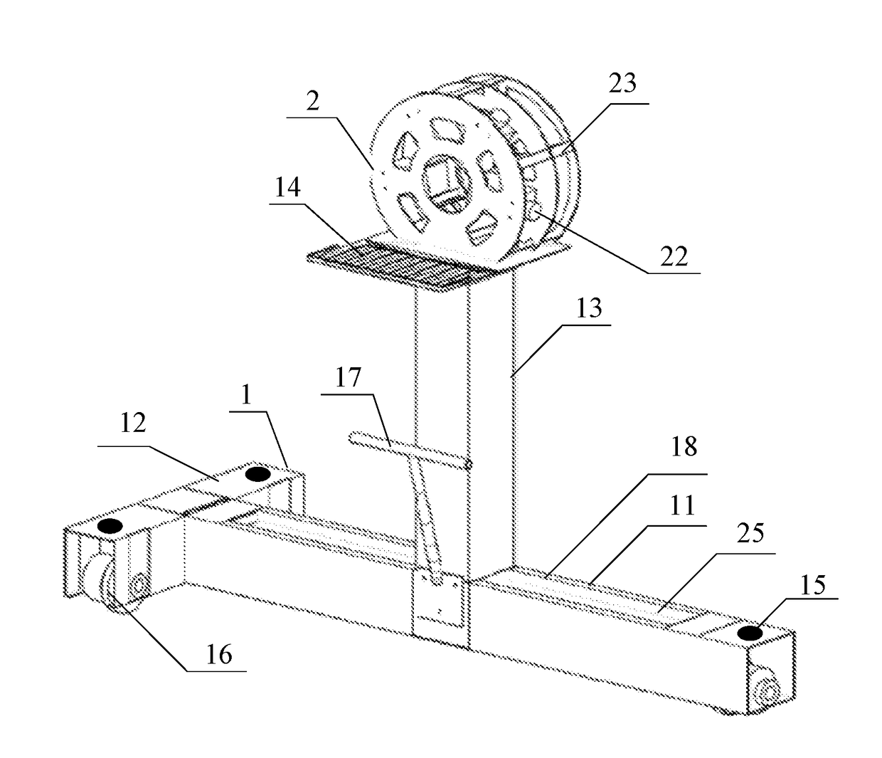
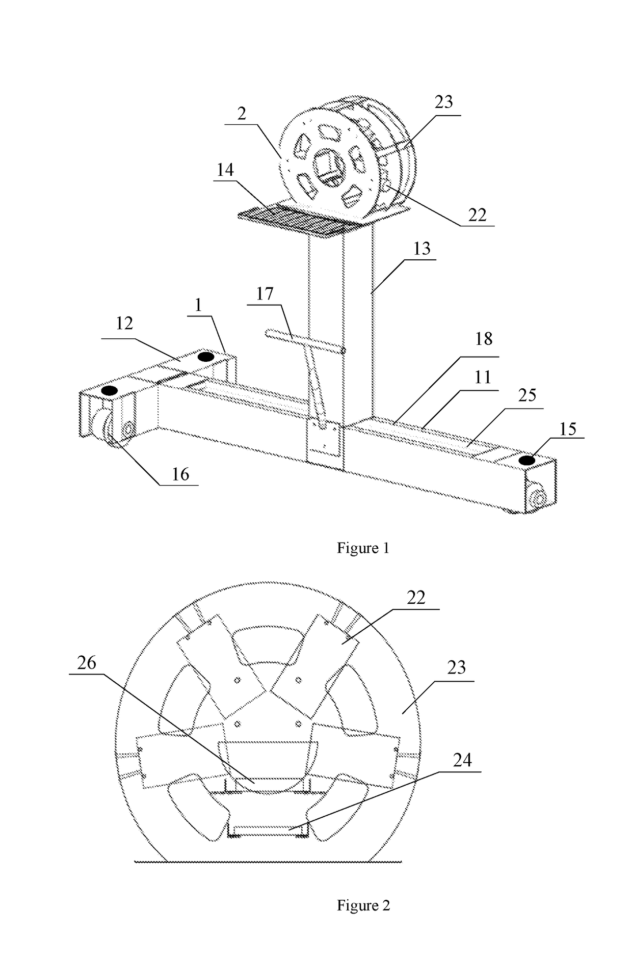
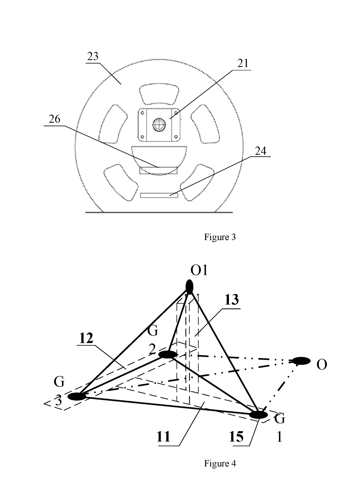
[0038]As shown in FIG. 1, a system for quickly detecting tunnel deformation includes a rail walking mechanism 1 and an acquisition system 2. The rail walking mechanism 1 is disposed on the subway rail. The rail walking mechanism 1 is a T-shaped walking platform, including a cross shaft 11, a longitudinal shaft 12 and a stand column 13; the cross shaft 11 and the longitudinal shaft 12 are connected via a sliding chute to form the T-shaped platform; and the cross shaft 11 and the upper surface of the longitudinal shaft 12 are positioned on the same plane. Three tread wheels 16 a...


PUM


Abstract

The present invention relates to a system for quickly detecting tunnel deformation, comprising a rail walking mechanism (1) disposed on a subway rail, and an acquisition system (2) disposed on the rail walking mechanism (1); wherein the rail walking mechanism (1) is a T-shaped walking platform, comprising a cross shaft (11), a longitudinal shaft (12) and a stand column (13); the cross shaft (11) and the longitudinal shaft (12) are connected to form the T-shaped platform; tread wheels (16) are disposed at the bottom of the T-shaped platform; one end of the stand column (13) is vertically connected with the cross shaft (11), and the other end of the stand column is used for configuring an operating platform (14) of the acquisition system (2); the acquisition system (2) comprises a fractional laser structured light source (21), industrial focus-fixed cameras (22) and a computer; and the computer is connected with the industrial focus-fixed cameras (22). Compared with the prior art, the quick detection device can effectively solve the problem of detecting cross section deformation of tunnels, the problem of transforming many different local coordinate systems to a global coordinate system, and the problem of unstable test data caused by movements.

Description

BACKGROUND OF THE INVENTIONTechnical Field[0001]The present invention is related to the technical field of civil engineering, specifically to a quick measurement system of cross section deformation of a subway tunnel structure, in particular to a system for quickly detecting tunnel deformation, which uses fractional laser as an auxiliary structured light source.Description of the Related Art[0002]When in use, cross sectional deformation in subway tunnels is an inevitable hazard and this hazard can cause invertible negative effects to the tunnel safety over time. Therefore, the maintenance of the tunnel structure during the subway operations is regarded as a necessary means for guaranteeing the long-term operational safety of the tunnels. The tunnel hazard detection is the basis of the decision-making for tunnel maintenance and the execution of the technical means.[0003]Traditionally, a total-station instrument method is usually employed to detect the cross section deformation of the...

Claims


Application Information

Patent Timeline
Patent Type & Authority Applications(United States)
IPC IPC(8): G01B11/16G01B11/00
CPCG01B11/16G01B11/002G01C15/002G01C7/06
Inventor YUAN, YONG
Owner TONGJI UNIV
Why Eureka
Try Eureka