
High-frequency module and communication apparatus

Active Publication Date: 2018-02-08
MURATA MFG CO LTD
View PDF3 Cites 14 Cited by
  • Summary
  • Abstract
  • Description
  • Claims
  • Application Information

AI Technical Summary

Benefits of technology

The invention provides high-frequency modules and communication devices that can increase signal strength without losing quality, while also being smaller and compatible with multiple bands.

Problems solved by technology

This configuration therefore poses an impediment to reduction in the high-frequency module in size.
When a matching circuit common to the plurality of filters is provided or when no matching circuit is provided for size reduction, it is difficult to perform impedance matching for the plurality of bands concurrently and characteristics can be deteriorated.
Therefore, with the configuration including the matching circuit common to the plurality of filters or the configuration including no matching circuit, it is extremely difficult to achieve both of suppression of deterioration in the NF and increase in the gain for the plurality of bands because of frequency characteristics and the like even when they can be achieved for only one band.

Method used


Image

  • High-frequency module and communication apparatus
  • High-frequency module and communication apparatus
  • High-frequency module and communication apparatus

Examples


Embodiment Construction

[0062]Hereinafter, preferred embodiments of the present invention and variations thereof will be described in detail with reference to the drawings. It should be noted that all of the preferred embodiments and variations which will be described below indicate comprehensive or specific examples. Numerical values, shapes, materials, components, arrangement and connection forms of the components, and the like which will be described in the following preferred embodiments and variations are examples and are not intended to limit the present invention. Components that are not described in independent claims among the components in the following preferred embodiments and variations are described as arbitrary components. The sizes or the size ratios of the components illustrated in the drawings are not necessarily strict or limited.

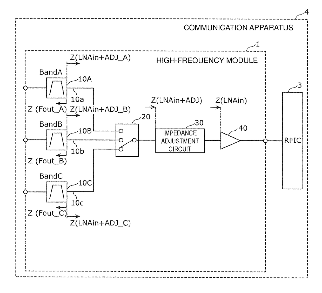
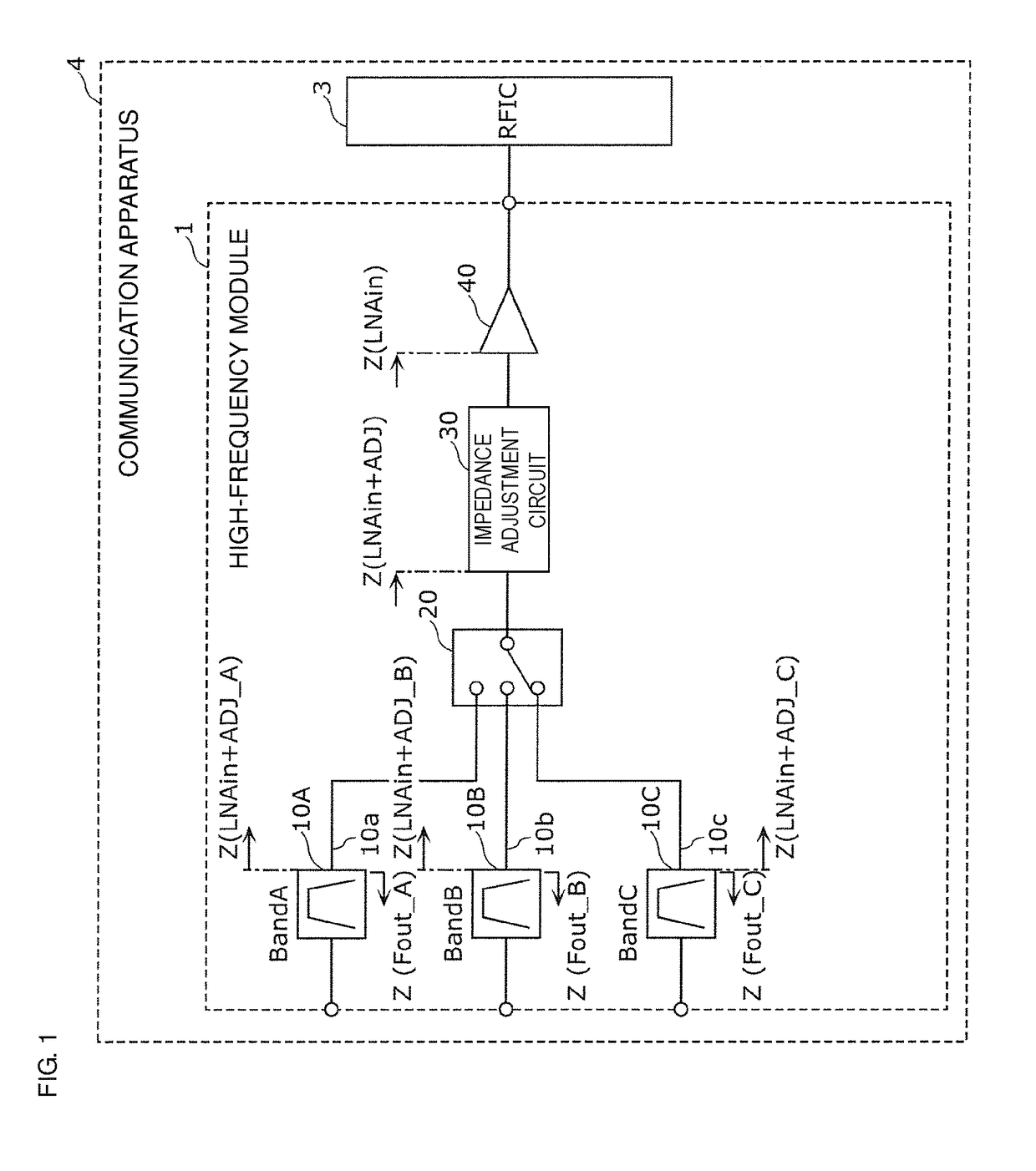
[0063]FIG. 1 is a circuit configuration diagram of a high-frequency module 1 according to a preferred embodiment of the present invention. FIG. 1 also illustrat...


PUM


Abstract

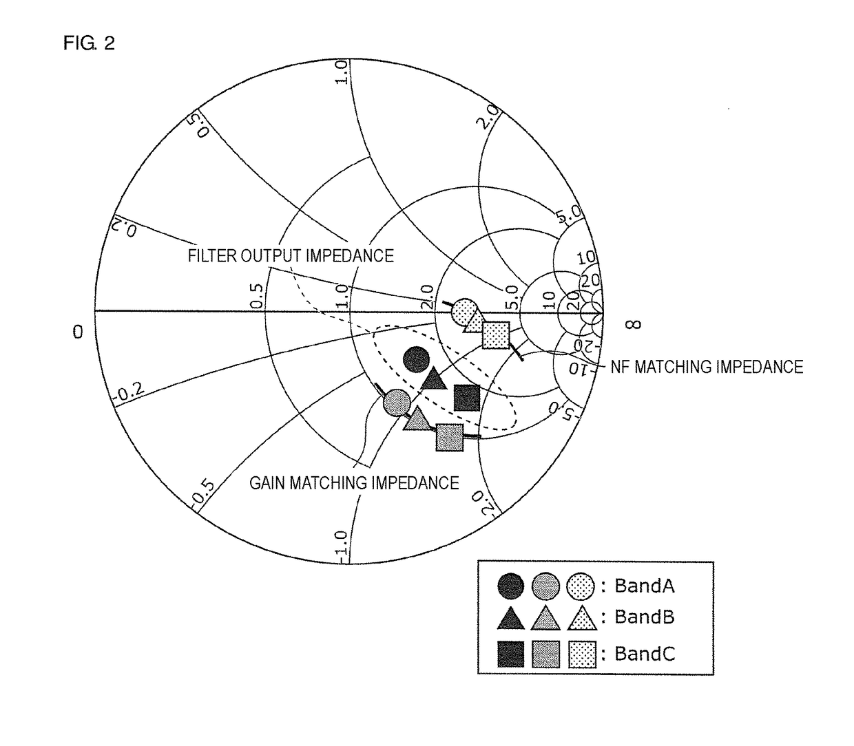
A high-frequency module includes a plurality of filters, a switch that commonly connects a plurality of paths, and a low noise amplifier that amplifies a high-frequency signal input from the plurality of filters with the switch interposed therebetween, wherein paths in which first and second filters are respectively provided among the plurality of paths connect the respective filters and the switch without connecting impedance elements, and each of the first and second filters has an output impedance located in a matching region between a NF matching impedance at which an NF of the low noise amplifier is minimum and a gain matching impedance at which a gain of the low noise amplifier is maximum in its respective pass band thereof on a Smith chart.

Description

CROSS REFERENCE TO RELATED APPLICATIONS[0001]This application claims the benefit of priority to Japanese Patent Application No. 2017-109028 filed on Jun. 1, 2017 and Japanese Patent Application No. 2016-155022 filed on Aug. 5, 2016. The entire contents of each application are hereby incorporated herein by reference.BACKGROUND OF THE INVENTION1. Field of the Invention[0002]The present invention relates to a high-frequency module and a communication apparatus that include a low noise amplifier.2. Description of the Related Art[0003]In a mobile communication terminal, an LNA (Low Noise Amplifier) generating less noise is used for a high-frequency module such as a reception-system front end circuit which handles a minute high-frequency signal in order to suppress deterioration in a NF (Noise Figure). A filter is provided at a previous stage of the LNA so as to transmit a desired frequency band such as a reception band and remove unnecessary frequency components.[0004]In the circuit conf...

Claims


Application Information

Patent Timeline
IPC IPC(8): H03F1/56H03F3/195
CPCH03F1/56H03F3/195H03F2200/451H03F2200/111H03F2200/222H03F2200/294H03F2200/165H03F1/26H03F2200/372H03H7/46
Inventor MUTO, HIDEKI
Owner MURATA MFG CO LTD
Learn More