

Method for manufacturing polishing head, polishing head, and polishing apparatus
a manufacturing method and technology of polishing head, applied in the direction of manufacturing tools, grinding devices, lapping machines, etc., can solve the problems of difficult control of the amount of incompressible fluid to be sealed in, the shape of the surface of rubber film cannot be constant, and the wafer cannot be uniformly pressed, etc., to achieve easy control of the amount of incompressible fluid, easy control, and excellent workability
Active Publication Date: 2018-02-15
SHIN-ETSU HANDOTAI CO LTD
View PDF0 Cites 3 Cited by
- Summary
- Abstract
- Description
- Claims
- Application Information
AI Technical Summary
Benefits of technology
The present invention is a method for manufacturing a polishing head that can reduce the amount of air remaining in the space section when sealing in a fluid. This method improves workability and allows for better control of the fluid amount. The polishing head made using this method has minimal air remaining, resulting in better control of the surface shape and improved wafer flatness and reproducibility. The use of this polishing head in a polishing apparatus provides the same benefits.
Problems solved by technology
That is because a pressure in a portion where the air is present is different from those in other portions when the air is mixed, the shape of the surface of the rubber film cannot be controlled to be constant, and the wafer cannot be uniformly pressed.
However, according to this technique, controlling an amount of the incompressible fluid to be sealed in is difficult.
Moreover, since the polishing head is assembled in the incompressible fluid, workability is considerably degraded.
Additionally, a polishing head which is used for polishing of a large-diameter wafer having a diameter of 300 mm or more has a large size and a very heavy weight, and hence a problem arises in a safety aspect as well as the workability.
Further, when the incompressible fluid to be sealed in is harmful to human bodies, work itself is impossible.
Method used
View moreImage
Smart ImageViewing Examples

Examples
examples
[0053]Although the present invention will now be more specifically described hereinafter with reference to an example and comparative examples of the present invention, the present invention is not restricted thereto.
Login to View More PUM
 Abstract
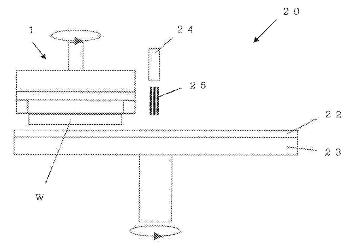
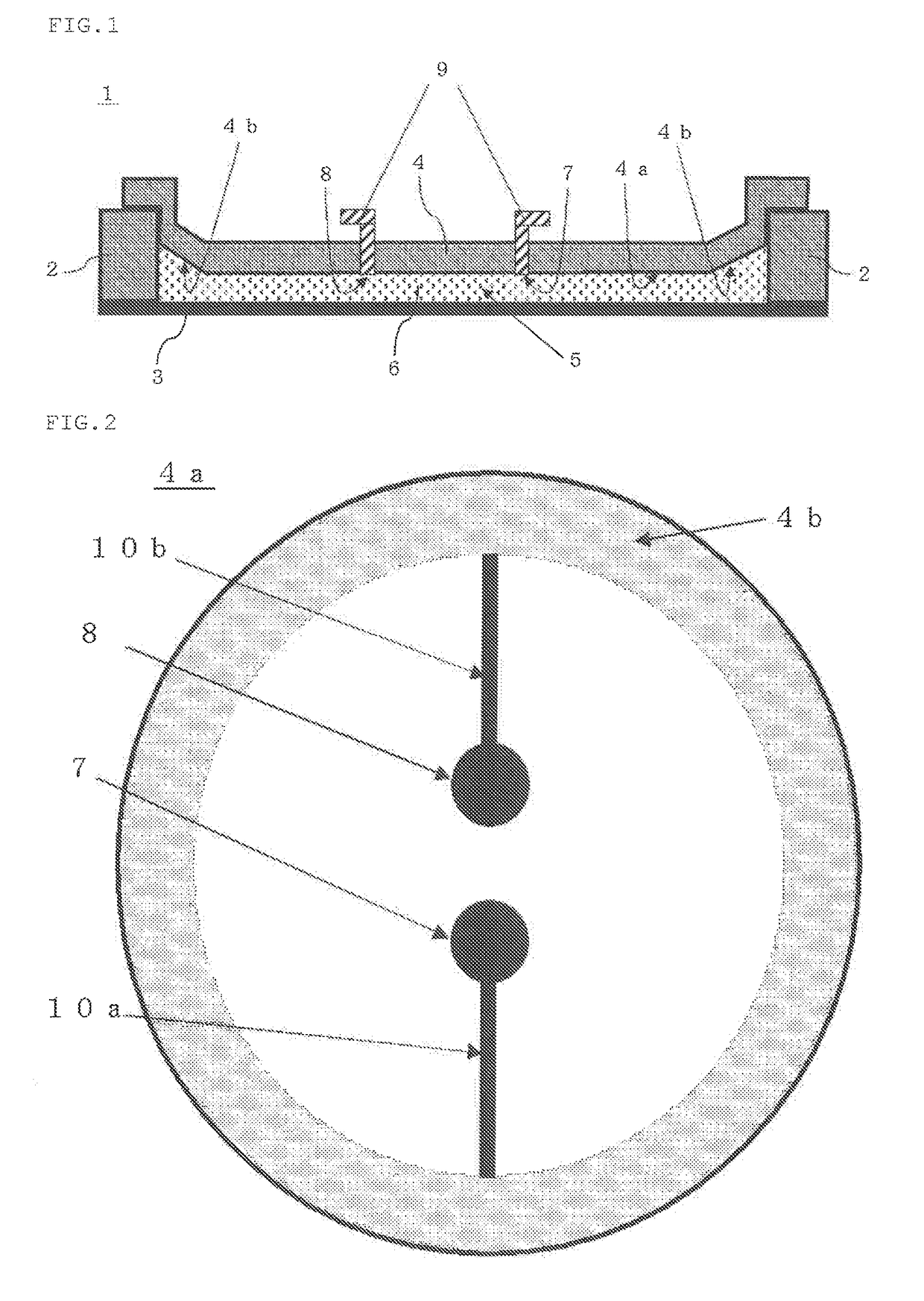
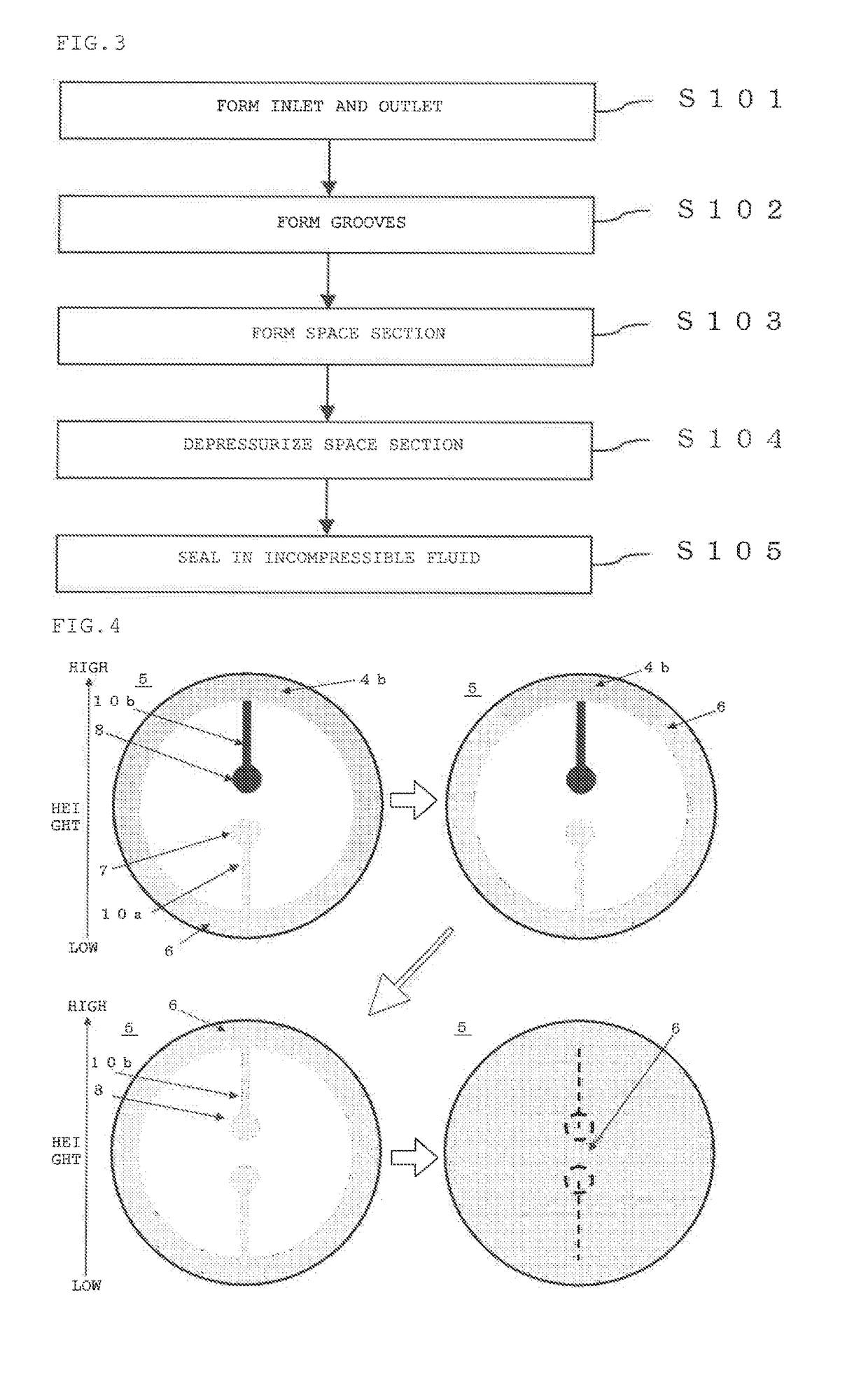
A method for manufacturing a polishing head, includes: forming, on a lower end surface of an intermediate plate, a groove which extends from an inlet of an incompressible fluid to an outer peripheral portion of the intermediate plate and a groove which extends from an outlet of air to the outer peripheral portion of the intermediate plate, also including, after attaching an elastic film to a lower end surface of a rigid ring and coupling an upper end surface of the rigid ring with the lower end surface of the intermediate plate to form a space section: depressurizing the inside of the space section; and discharging the air in the space section from the outlet while pouring the incompressible fluid into the space section from the inlet after the depressurizing, and closing the inlet and outlet to seal the incompressible fluid in the space section.
Description
TECHNICAL FIELD[0001]The present invention relates to a method for manufacturing a polishing head, a polishing head, and a polishing apparatus including the polishing head,BACKGROUND ART[0002]In recent years, a demand concerning flatness of a wafer such as a silicon wafer has been increased more than ever, and fabricating a wafer having higher flatness in single-side polishing has been demanded. Further, to provide a wafer having high flatness with excellent reproducibility, a polishing head including a rubber film which holds the wafer, a space section which is in contact with the rubber film, and an incompressible fluid which is sealed in the space section is used (see, e.g., Patent Literature 1).[0003]According to such a polishing head, since a shape of a surface of the rubber film can be appropriately adjusted by the incompressible fluid, when the surface of the rubber film is appressed against an entire back surface of the wafer to press the wafer, polishing can be carried out....
Claims
Login to View More Application Information
Patent Timeline
 Patent Type & AuthorityApplications(United States)
IPC IPC(8): B24B37/26B24B37/24B24D18/00
CPCB24B37/26B24D18/0045B24B37/24B24B37/04B24B37/30B24D18/0027B24B41/06H01L21/304
InventorOSEKI, MASAAKISATO, MICHITO
OwnerSHIN-ETSU HANDOTAI CO LTD