Eureka AIR delivers breakthrough ideas for toughest innovation challenges, trusted by R&D personnel around the world.

Detachable transformer

Active Publication Date: 2018-02-15
MEANWELL GUANGZHOU ELECTRONICS
View PDF4 Cites 0 Cited by
  • Summary
  • Abstract
  • Description
  • Claims
  • Application Information

AI Technical Summary

Benefits of technology

The present invention is a detachable transformer that allows for easy replacement of certain parts, such as a second bobbin. This results in faster manufacturing, lower costs, and larger production runs with lower eddy current loss. Essentially, the detachable transformer allows for easy customization and improved efficiency.

Problems solved by technology

If the windings of the transformer are formed by wires, the winding corresponding to large current is difficult to manufacture, and its output pins having large volumes are not easy to manufacture.
Besides, the wires for large current are thicker and difficult to wind around the pins.
Even the thick wires are wound around the pins, the large current flowing through the circuit board can still cause loss.
Hence, the transformer and a conduction case above can cause eddy current loss.

Method used


Image

  • Detachable transformer
  • Detachable transformer
  • Detachable transformer

Examples


Embodiment Construction

[0021]Reference will now be made in detail to embodiments illustrated in the accompanying drawings. Wherever possible, the same reference numbers are used in the drawings and the description to refer to the same or like parts. In the drawings, the shape and thickness may be exaggerated for clarity and convenience. This description will be directed in particular to elements forming part of, or cooperating more directly with, methods and apparatus in accordance with the present disclosure. It is to be understood that elements not specifically shown or described may take various forms well known to those skilled in the art. Many alternatives and modifications will be apparent to those skilled in the art, once informed by the present disclosure.

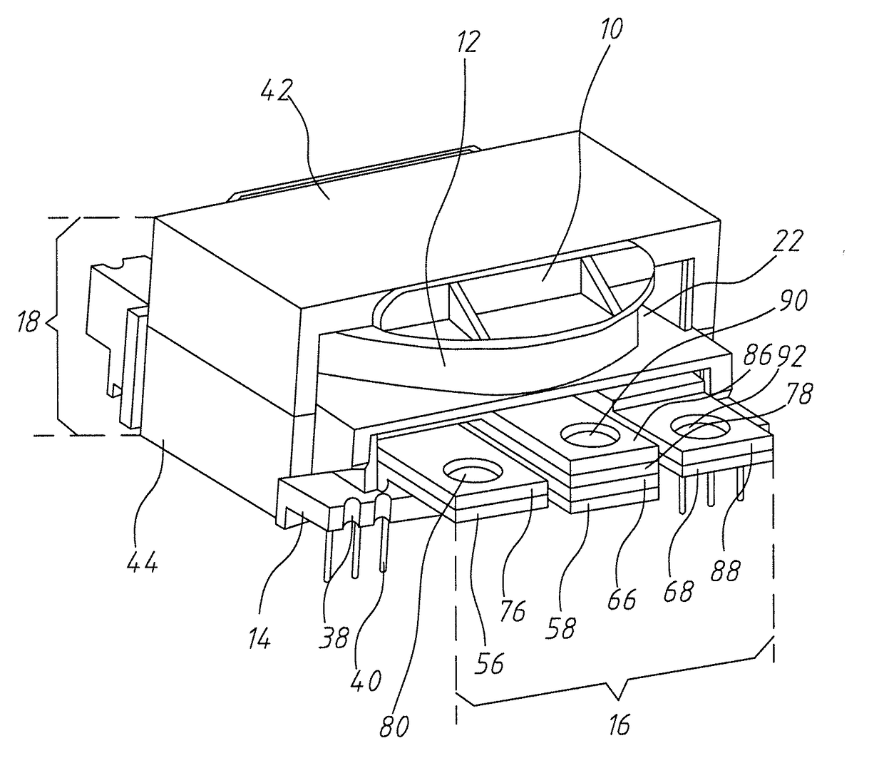
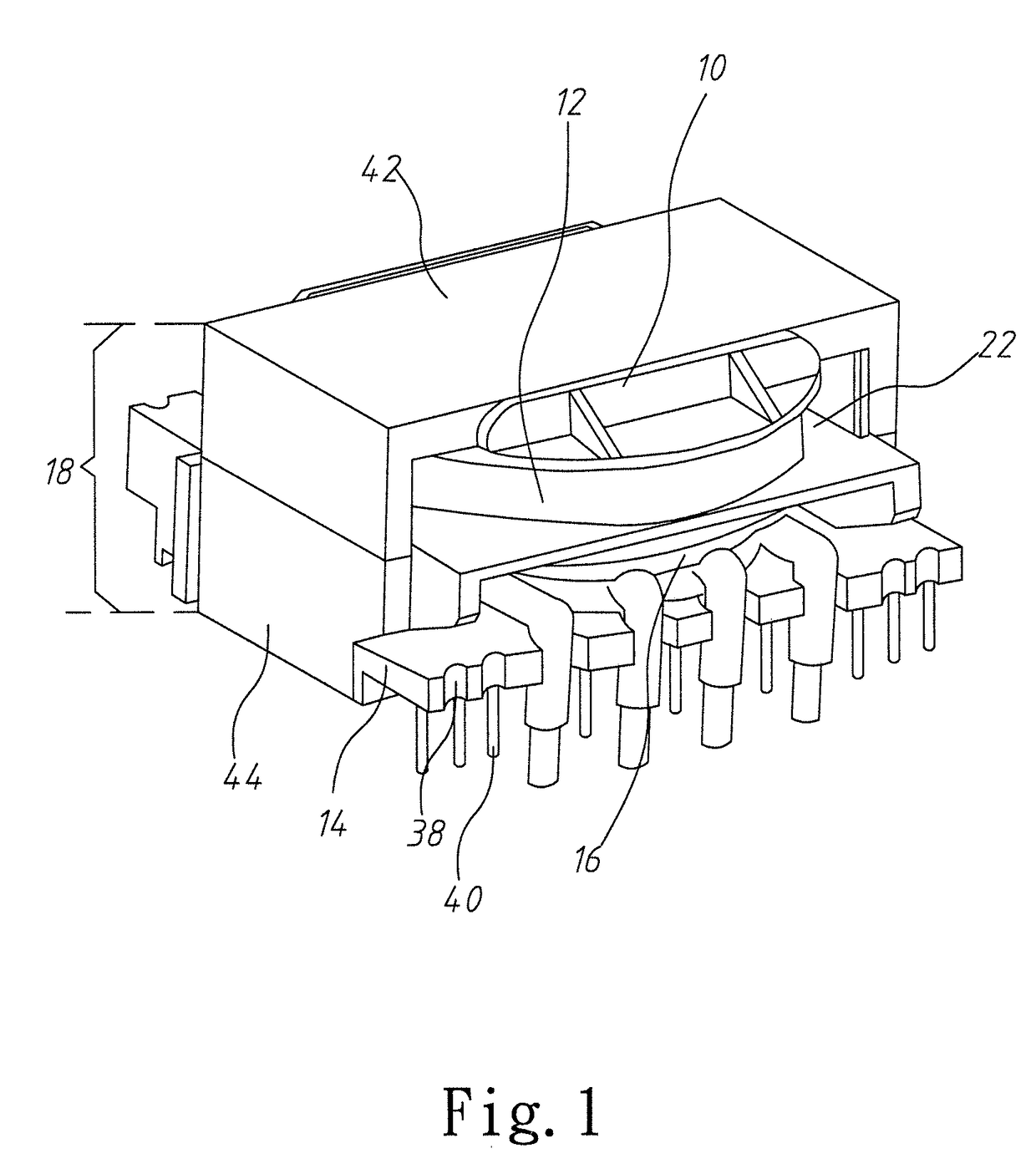
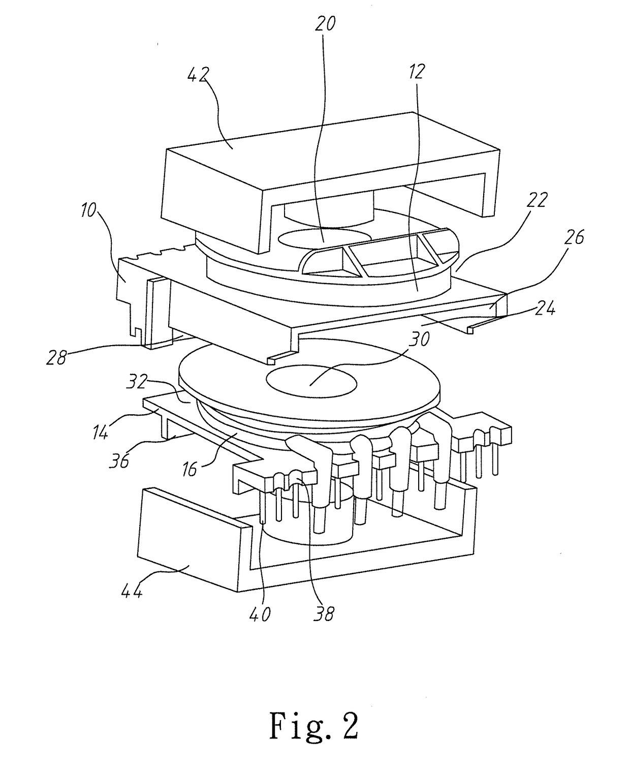
[0022]Refer to FIG. 1, FIG. 2 and FIG. 3. The detachable transformer of the first embodiment of the present invention is introduced as below. The first embodiment is used to output high voltage and low current. For example, the low current has a ...


PUM


Abstract

A detachable transformer includes a first bobbin, a primary winding, a second bobbin, a secondary winding and a magnetic core set. The magnetic core set peripherally surrounds the first bobbin and the second bobbin and is inserted into them. A top and a bottom of the first bobbin respectively have a first winding recess and an installation recess. The primary winding is arranged in the first winding recess. A side of the installation recess has a first opening connecting with an external space. A top of the second bobbin has a second winding recess. The secondary winding is arranged in the second winding recess. The second bobbin is arranged in the installation recess through the first opening, whereby the first bobbin and the second bobbin form a detachable connection.

Description

BACKGROUND OF THE INVENTIONField of the Invention[0001]The present invention relates to a transformer, particularly to a detachable transformer.Description of the Related Art[0002]With the development and evolution of electronic produces, different electronic produces are driven by different power devices. Thus, the industries of the power devices actively try to develop various transformer structures and apply them to various power supplies.[0003]A simple transformer consists of a first conductor and a second conductor. When a varying current flows through the first conductor, a varying magnetic field impinges on the first conductor. Then, based on the electromagnetic mutual induction principle, the varying magnetic field induces a varying electromotive force (EMF) or voltage in the second conductor, thereby establishing a voltage drop between the first conductor and the second conductor. With the development of technology products, the transformers are not only used to vary the EM...

Claims


Application Information

Patent Timeline
IPC IPC(8): H01F27/34H01F29/00H01F27/24H01F27/32H01F27/28
CPCH01F27/34H01F27/325H01F2027/348H01F27/24H01F29/00H01F27/2823H01F27/2866
Inventor LEE, YU-HSIANGCHANG, CHEN-FENG
Owner MEANWELL GUANGZHOU ELECTRONICS
Why Eureka
Eureka Blog
Learn More