
Flexible flat cable and method for manufacturing the same

a flat cable, flexible technology, applied in the direction of power cables, cables, insulated conductors, etc., can solve the problems of limited usage field of coaxial cables, signal crosstalk may occur, signal shielding may not be completely accomplished, etc., to achieve the effect of small width

Active Publication Date: 2018-02-22
SAMSUNG ELECTRONICS CO LTD
View PDF6 Cites 20 Cited by
  • Summary
  • Abstract
  • Description
  • Claims
  • Application Information

AI Technical Summary

Benefits of technology

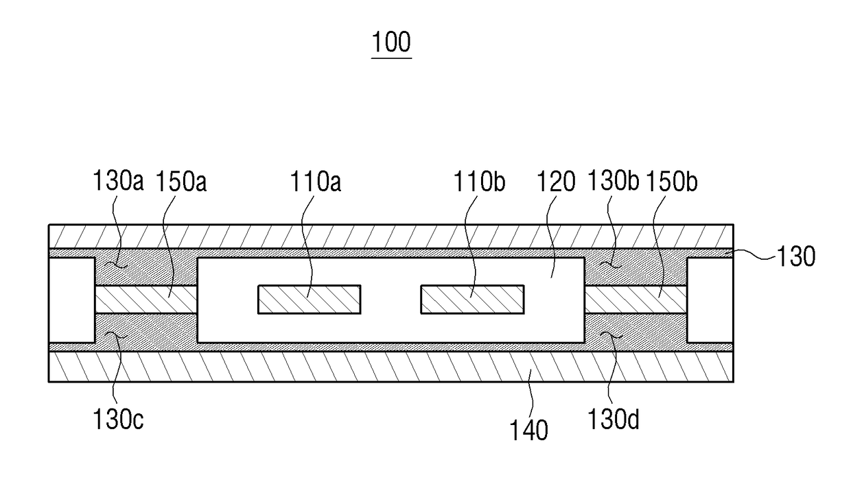
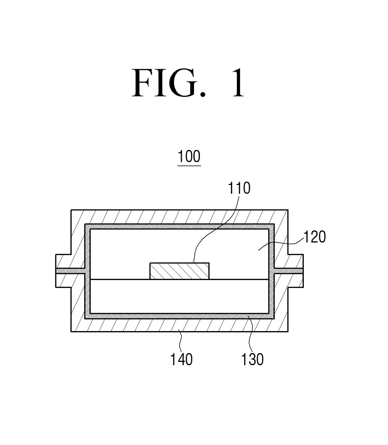
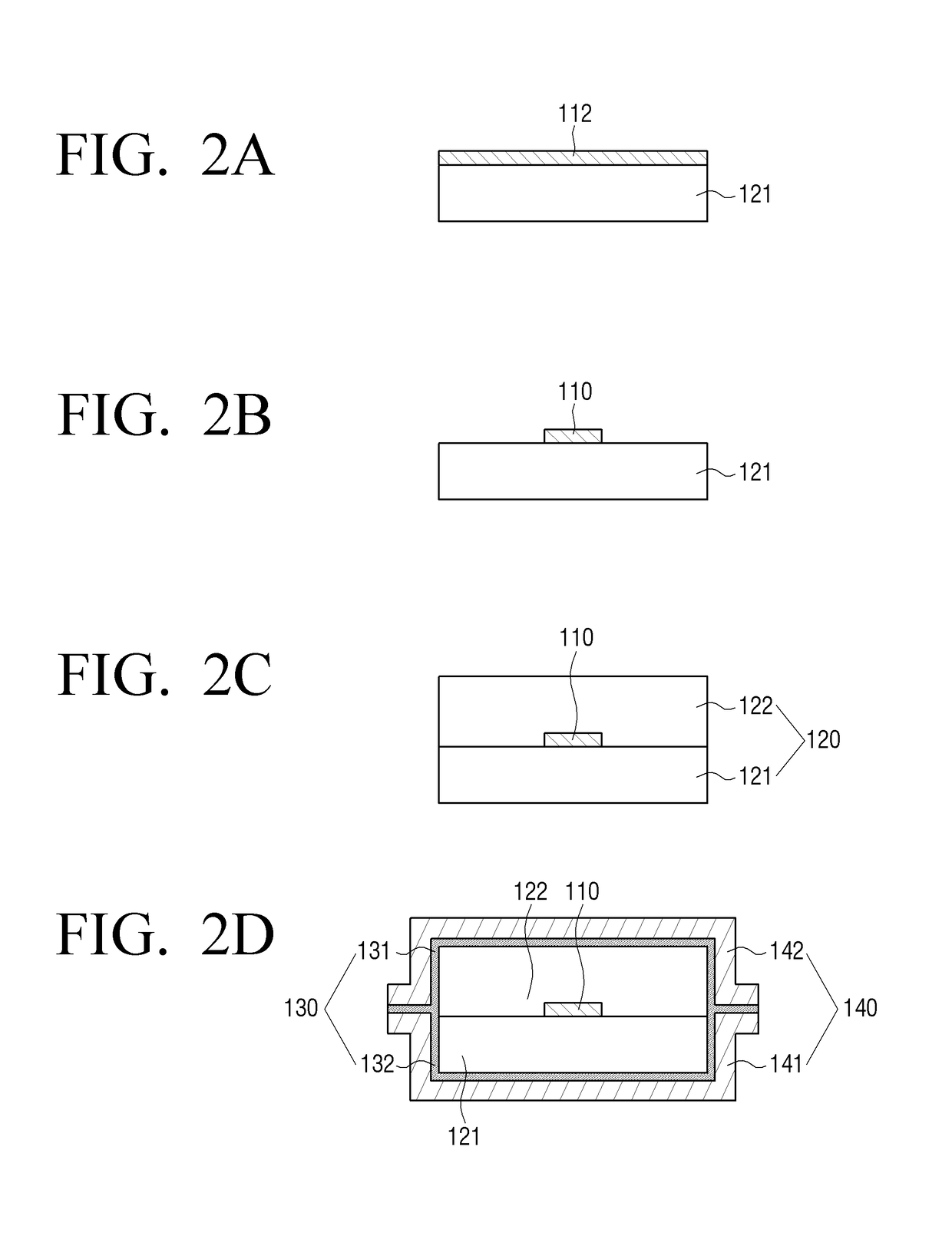
The patent text describes a flexible flat cable with a shield film and a conductive adhesive layer, and a method for manufacturing it. The cable has various signal transmission lines and ground parts, and the conductive adhesive layer covers them all. The cable has a cross section of each ground part and signal transmission part that matches the shape of a strip line. The method involves providing a copper thin film layer, etching a portion of it, laminating a second coverlay on top, and covering the entire cable with a shield film to which conductive adhesive is applied. The technical effects of this patent include improved signal transmission and grounding, as well as simplified manufacturing process.

Problems solved by technology

But the coaxial cables may have a limited usage field due to the high cost.
However, the related flexible flat cables may not completely cover signal lines and thus shielding on the signals may not be completely accomplished.
Accordingly, crosstalk between signals may be caused.
Cables that a conductive material is filled within a via formed by etching a printed circuit board (PCB) may not also completely cover signal lines and thus a shielding efficiency may be degraded.

Method used


Image

  • Flexible flat cable and method for manufacturing the same
  • Flexible flat cable and method for manufacturing the same
  • Flexible flat cable and method for manufacturing the same

Examples


Embodiment Construction

[0053]Various example embodiments will now be described in greater detail with reference to the accompanying drawings in which various embodiments are illustrated. The techniques described herein are examples, and should not be construed as implying any particular limitation on the present disclosure. It should be understood that various alternatives, equivalents and / or modifications could be devised by those skilled in the art. In the following disclosure, unless otherwise described, the same reference numerals are used for the same elements when they are depicted in different drawings.

[0054]It will be understood that, although the terms first, second, etc. may be used herein in reference to elements of the disclosure regardless of an order and / or importance, such elements should not be construed as limited by these terms. The terms are used only to distinguish one element from other elements. For example, without departing from the spirit of the disclosure, a first element may ref...


PUM


Abstract

A flexible flat cable and a manufacturing method thereof are provided. The flexible flat cable includes a plurality of ground parts comprising a conductive material disposed at intervals, a plurality of signal transmission parts comprising a conductive material disposed between the plurality of ground parts, an outer skin covering the signal transmission parts and the ground parts, and a conductive adhesive layer disposed between the ground parts and the signal transmission parts and the outer skin part, the signal transmission part comprising an insulating member and a strip line disposed within the insulating member and the ground part comprising a ground member having the same cross section as the strip line and a conductive adhesive block coupled to the ground member with the conductive adhesive layer.

Description

CROSS-REFERENCE TO RELATED APPLICATIONS[0001]This application is based on and claims priority under 35 U.S.C. §119 to Korean Patent Application No. 10-2016-0103808, filed on Aug. 16, 2016 in the Korean Intellectual Property Office and Korean Patent Application No. 10-2017-0043851, filed on Apr. 4, 2017, in the Korean Intellectual Property Office, the disclosures of which are incorporated by reference herein in their entireties.BACKGROUNDField[0002]The present disclosure relates generally to a flexible flat cable, and for example, to a flexible flat cable and a method for manufacturing the same.Description of Prior Art[0003]Coaxial cables have been used to shield signals in the related arts. But the coaxial cables may have a limited usage field due to the high cost. The related flexible flat cables using an impedance matching film may be cheaper than the coaxial cables. However, the related flexible flat cables may not completely cover signal lines and thus shielding on the signals m...

Claims


Application Information

Patent Timeline
IPC IPC(8): H01P3/08H01B7/08H01P11/00H01B13/00
CPCH01P3/08H01B7/0807H01B13/0036H01P11/003H01B7/0823H01P3/085H01P5/028H05K1/0218H05K2201/0715H05K1/148H05K1/0245H05K2201/058H05K1/0221H01B7/08H01B7/04H01B9/028H01B7/02H01B13/0026
Inventor BAE, BUM-HEEKWON, YOUNG-KUN
Owner SAMSUNG ELECTRONICS CO LTD
Learn More