Reactor including first end plate and second end plate

a technology of end plates and reactors, applied in the field of reactors, can solve the problems of leakage of magnetic flux, difficult control of gap lengths affecting inductance, and complicated configuration of reactors b>100/b>

Active Publication Date: 2018-03-08
FANUC LTD
View PDF2 Cites 8 Cited by
  • Summary
  • Abstract
  • Description
  • Claims
  • Application Information

AI Technical Summary

Benefits of technology

[0007]FIG. 10 is an enlarged side view of the gap. In FIG. 10, to configure the reactor 100, the outer side leg portions 151 and 161 are coupled to each other by coupling plates 181 and 182. It is assumed that similarly, the other leg portions are configured as well. However, in such a

Problems solved by technology

However, in such a case, a configuration of the reactor 100 becomes complicated.
As a result, it is difficult to control a gap length which influences t

Method used


Image

  • Reactor including first end plate and second end plate
  • Reactor including first end plate and second end plate
  • Reactor including first end plate and second end plate

Examples


Embodiment Construction

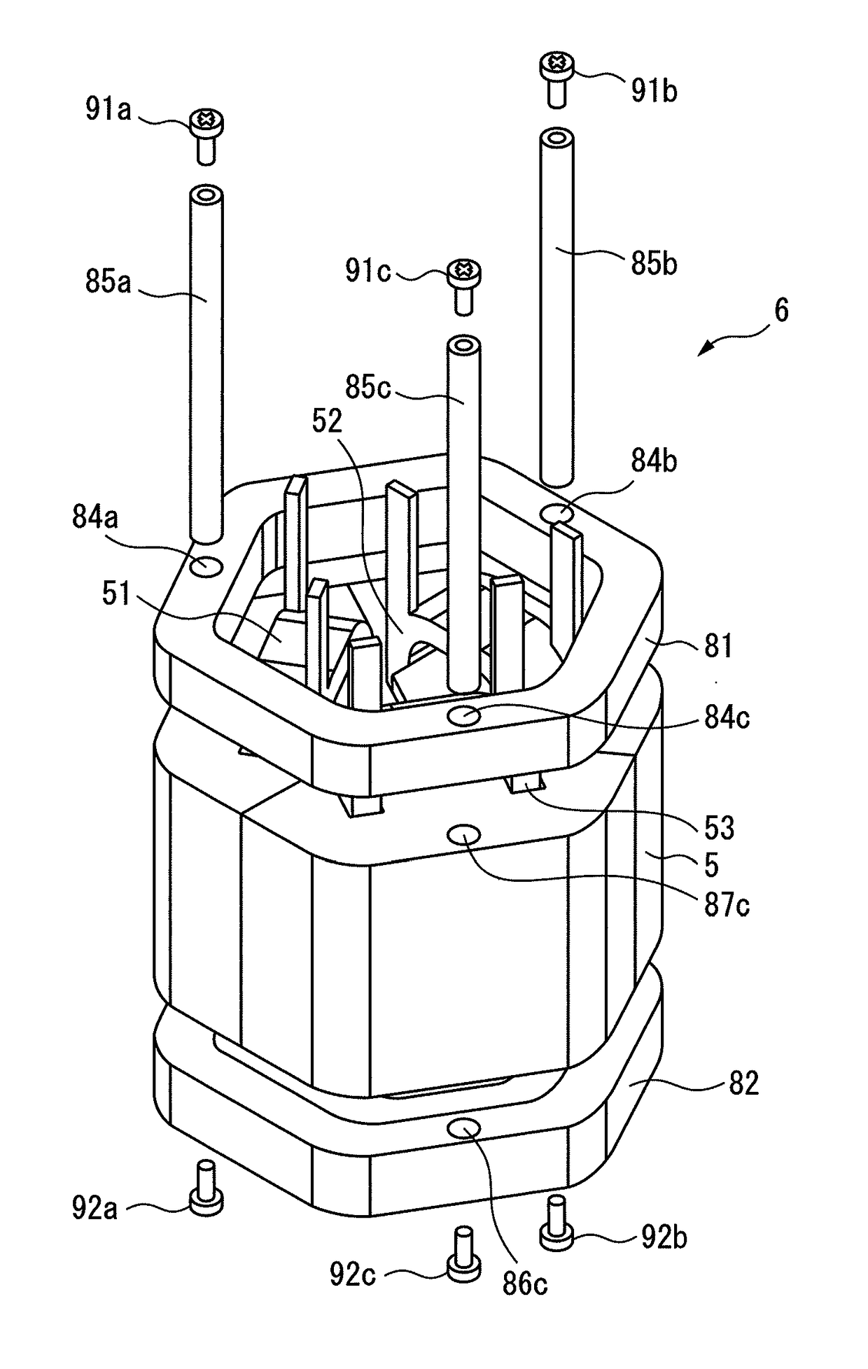
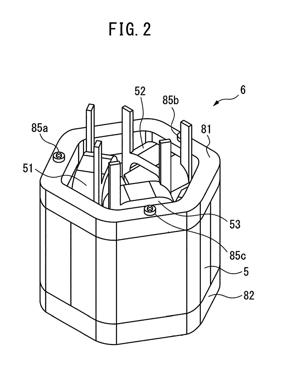
[0038]Hereinafter, embodiments of the present invention will be described with reference to the attached drawings. In the following figures, similar members are assigned similar reference signs. To facilitate understanding, these figures are suitably changed in scale.

[0039]In the following description, a three-phase reactor will be described by way of example, while application of the present invention is not limited to the three-phase reactor but application can be widely made to a multiphase reactor in each phase of which constant inductance is to be provided. In addition, the reactor of the present invention is not limited to that as provided on the primary side and the secondary side of an inverter in an industrial robot or a machine tool, but can be applied to various devices.

[0040]FIG. 1 is an exploded perspective view of a reactor according to the present invention, and FIG. 2 is a perspective view of the reactor illustrated in FIG. 1. A reactor 6 illustrated in FIGS. 1 and 2...


PUM


Abstract

A reactor includes a core body; a first end plate and a second end plate which sandwich and fasten the core body; and a plurality of axis portions disposed in the vicinity of an outer edge portion of the core body or outward of the core body and supported by the first end plate and the second end plate.

Description

BACKGROUND OF THE INVENTION1. Field of the Invention[0001]The present invention relates to a reactor. In particular, the present invention relates to a reactor in which a core body is held between a first end plate and a second end plate.2. Description of the Related Art[0002]FIG. 8 is a perspective view of a reactor according to a conventional technique as disclosed in Japanese Unexamined Patent Publication (Kokai) No. 2000-77242 and Japanese Unexamined Patent Publication (Kokai) No. 2008-210998. As illustrated in FIG. 8, a reactor 100 includes a substantially E-shaped first iron core 150 including two first outer side leg portions 151, 152 and a first center leg portion 153 disposed between the first outer side leg portions 151, 152 and a substantially E-shaped second iron core 160 including two second outer side leg portions 161 and 162 and a second center leg portion 163 disposed between the second outer side leg portions 161 and 162. The first iron core 150 and the second iron ...

Claims


Application Information

Patent Timeline
IPC IPC(8): H01F27/255H01F27/26H01F41/02H01F37/00H01F27/32
CPCH01F27/255H01F27/263H01F41/02H01F37/005H01F27/324H01F3/14H01F27/245H01F27/266H01F27/306H01F27/28
Inventor MAEDA, TAKUYASHIROUZU, MASATOMOKAJIYA, TAKAFUMI
Owner FANUC LTD
Why Eureka
Try Eureka