Horizontal alignment-type liquid crystal display device

a liquid crystal display and horizontal alignment technology, applied in the direction of instruments, polarising elements, other domestic objects, etc., can solve the problems of inability to obtain sufficient optical compensation, difficulty in achieving sufficient thinning effect, and increase in total layers

Active Publication Date: 2018-03-22
FUJIFILM CORP
View PDF6 Cites 5 Cited by
  • Summary
  • Abstract
  • Description
  • Claims
  • Application Information

AI Technical Summary

Benefits of technology

[0007]An object of the present invention is to provide a horizontal alignment-type liquid crystal display device in which thinning is effectively realized and a liquid crystal cell can be sealed as a horizontal alignment-type liquid crystal display device having a resin substrate. Another object of the present invention is to provide a horizontal alignment-type liquid crystal display device having optical compensation corresponding to a configuration having a resin substrate.
[0026]According to the present invention, it is possible to provide a horizontal alignment-type liquid crystal display device in which thinning is effectively realized and a liquid crystal cell can be sealed, as a horizontal alignment-type liquid crystal display device having a resin substrate. In the horizontal alignment-type liquid crystal display device according to the present invention, it is possible to perform optical compensation corresponding to a configuration having a resin substrate.

Problems solved by technology

In a liquid crystal display device having a resin substrate, with a configuration using an optical compensation film for improving display performances together with a gas barrier film for sealing, the number of total layers increases, and it is difficult to sufficiently obtain a thinning effect based on the use of the resin substrate.
However, even in a case where an optical design according to a report in a related art disclosed in JP2006-521570A derived from a phase difference of a resin substrate is performed in a horizontal alignment-type liquid crystal display device using a resin substrate, there has been a problem in that sufficient optical compensation was not able to be obtained.

Method used


Image

  • Horizontal alignment-type liquid crystal display device
  • Horizontal alignment-type liquid crystal display device
  • Horizontal alignment-type liquid crystal display device

Examples


example 1

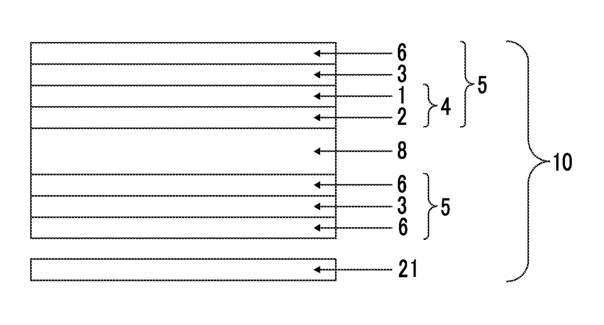
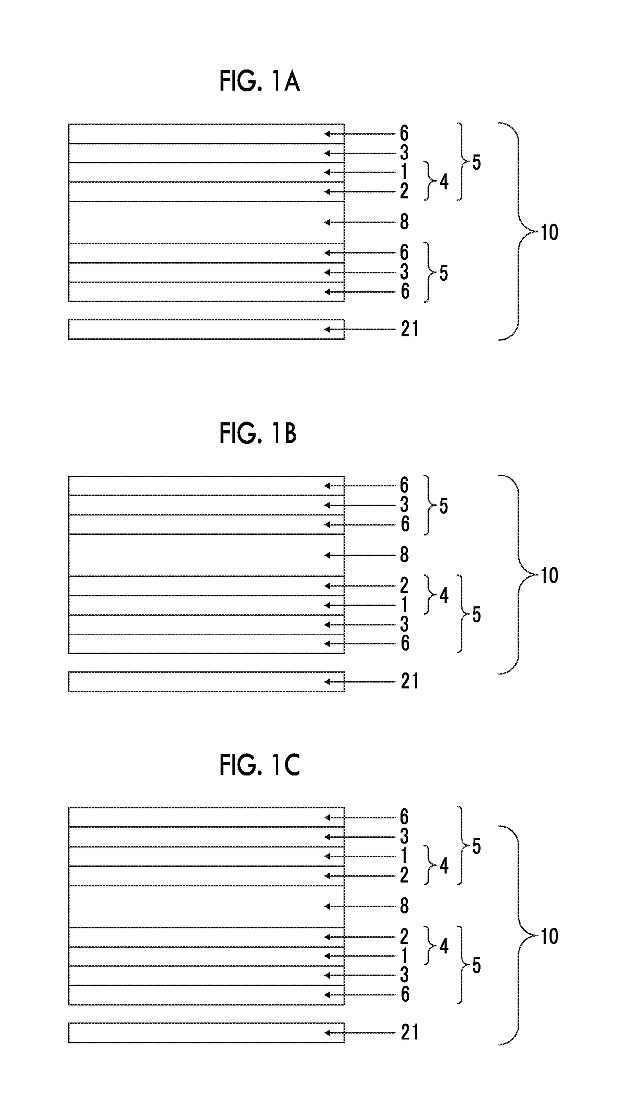
[0240]An inorganic layer was formed on the surface of the stretched styrene-maleic acid anhydride copolymer film 3 opposite to the side in contact with the endless metal belt. The polystyrene film 1 was coated with the adhesive solution 1. The inorganic layer side of the stretched styrene-maleic acid anhydride copolymer film 2 on which the inorganic layer was formed was adhered as a bonding surface, so as to manufacture a laminate film for Example 1.

example 2

[0241]A laminated film for Example 2 was obtained in the same manner as in Example 1 except for using the polystyrene film 2 instead of the polystyrene film 1.

example 3

[0242]An inorganic layer was formed on the surface of the stretched styrene-maleic acid anhydride copolymer film 3 opposite to the side which was in contact with the endless metal belt, and this was used as a laminated film for Example 3.


PUM

PropertyMeasurementUnit
thicknessaaaaaaaaaa
thicknessaaaaaaaaaa
thicknessaaaaaaaaaa

Abstract

The present invention provides a horizontal alignment-type liquid crystal display device including a viewing-side polarizing plate; a liquid crystal cell; a backlight-side polarizing plate; and a backlight, in this order, the liquid crystal cell includes a liquid crystal layer held between two substrates, at least any one of the substrates is a resin substrate, the polarizing plate provided on the resin substrate side includes a gas barrier film including a phase difference layer and an inorganic layer, and a polarizer, and the gas barrier film is on the resin substrate side with respect to the polarizer. In the horizontal alignment-type liquid crystal display device according to the present invention, thinning based on the use of the resin substrate is effectively realized, and a liquid crystal cell can be sealed.

Description

CROSS-REFERENCE TO RELATED APPLICATIONS[0001]This application is a continuation of PCT International Application No. PCT / JP2016 / 065657 filed on May 27, 2016, which claims priorities under 35 U.S.C § 119 (a) to Japanese Patent Application No. 2015-108260 filed on May 28, 2015 and Japanese Patent Application No. 2016-007236 filed on Jan. 18, 2016, the entire contents of which are incorporated herein by reference.BACKGROUND OF THE INVENTION1. Field of the Invention[0002]The present invention relates to a horizontal alignment-type liquid crystal display device.2. Description of the Related Art[0003]As a substitution for a glass substrate of a liquid crystal cell of a liquid crystal display device, various resin (plastic) substrates are reviewed. According to the use of the resin substrate, the thinning and the flexibility of the liquid crystal display device can be realized. However, the resin substrate has inferior gas barrier properties shielding oxygen or water vapor than a glass sub...

Claims


Application Information

Patent Timeline
Patent Type & Authority Applications(United States)
IPC IPC(8): G02F1/13363B32B27/06G02F1/1335G02F1/1333
CPCG02F1/13363B32B27/06G02F1/133528G02F1/133305B32B2457/202B32B2307/42G02F2001/133562G02F2001/133567G02F2413/02G02F2413/06G02B5/30G02F1/133634G02F2201/501G02F1/133738G02F1/133562G02F1/133567
Inventor KAMO, MAKOTO
Owner FUJIFILM CORP
Why Eureka
Try Eureka