Desalting Method and Apparatus

a hydrocarbon feedstock and desalting method technology, applied in the direction of material analysis using wave/particle radiation, refining by water treatment, instruments, etc., can solve the problems of significant damage to refinery equipment, damage commonly observed in the lines, and considerable time and cost involved in replacing damaged refinery equipmen

Inactive Publication Date: 2018-03-29
BP CORP NORTH AMERICA INC
View PDF2 Cites 1 Cited by
  • Summary
  • Abstract
  • Description
  • Claims
  • Application Information

AI Technical Summary

Problems solved by technology

Chloride salts are typically found in crude oil and pose a particular problem, since they can form hydrochloric acid.
Over time, corrosive acids can cause significant damage to refinery equipment.
Damage is commonly observed in the lines that transport crude oil from one area of a refinery to another.
Considerable time and cost may be involved in replacing damaged refinery equipment.
However, such methods are limited by the accuracy of the input data.

Method used


Image

  • Desalting Method and Apparatus
  • Desalting Method and Apparatus
  • Desalting Method and Apparatus

Examples


example 1

of the Line in the First Desalting Process

[0092]Operating conditions at the time of sampling in the first stage are shown in Table 1:

Amount ofwash waterCrudeWash wateradded (% byDeltaValveflowCruderate (barrels / volume ofpressureopen(barrels / velocityhour)crude oil)(psi)(%)hour)(m / s)East2555.51619.54,6251.55mixingvalveWest2645.715.816.54,6251.55mixingvalve

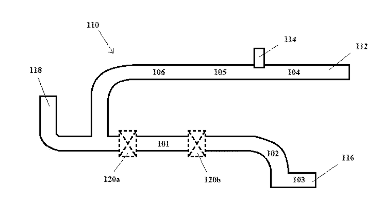
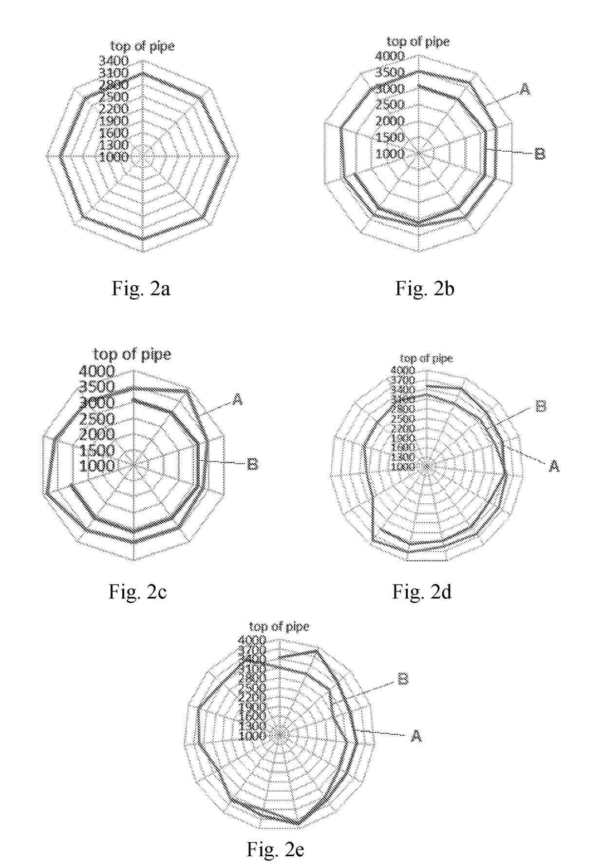
[0093]The radar plot shown in FIG. 2a shows the results of spectra obtained at the crude oil inlet (see location 1 of FIG. 1), i.e. upstream of the wash water inlet. The crude oil contained 3% residual water. This water was injected upstream of cold preheat exchangers. The radar plot shows that the oil and water were mixed uniformly with no distinct water or crude oil phase.

[0094]The radar plots shown in FIGS. 2b-e show the results of spectra obtained at a number of locations (locations 5, 2, 6 and 7 as shown in FIG. 1, respectively). Spectra were obtained at a point in time before the addition of wash water to the system (denoted in...

example 2

of the Line in the Second Desalting Process

[0101]Operating conditions at the time of sampling in the second stage are shown in Table 2:

Amount ofwash waterCrudeWash wateradded (% byDeltaValveflowCruderate (barrels / volume ofpressureopen(barrels / velocityhour)crude oil)(psi)(%)hour)(m / s)Mixing4755.116-16.525.09,2503.14valve

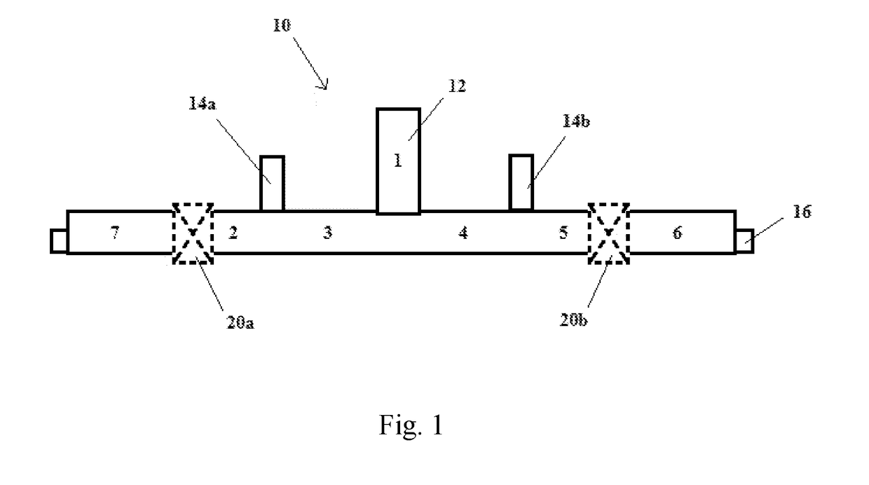
[0102]The radar plot shown in FIG. 5a shows the results of spectra obtained at the crude oil inlet (see location 4 of FIG. 4), i.e. upstream of the wash water inlet. It can be seen that the counts obtained from the line in the second stage were lower than those obtained from the line in the first stage. This difference was due to the amount of water in the crude feeds. Whilst the first stage raw crude oil included 3% residual water, the second stage crude oil feed contained a smaller amount of water (just that carried over from the first stage desalter).

[0103]The radar plots shown in FIG. 5b were obtained upstream of a wash water inlet (at location 4 as shown in FIG. ...


PUM

PropertyMeasurementUnit
angleaaaaaaaaaa
angleaaaaaaaaaa
angleaaaaaaaaaa

Abstract

A method for optimizing a desalting process in which a hydrocarbon feedstock is passed to a desalter through a line under a set of conditions, the hydrocarbon feedstock containing a hydrocarbon fluid, water and a salt, said method comprising: obtaining spectra of the hydrocarbon feedstock under a plurality of environments in the line; comparing the spectra; and based on the comparison of the spectra, either modifying or maintaining the set of conditions under which the hydrocarbon feedstock is passed to the desalter; wherein the spectra are obtained using neutron backscattering.

Description

FIELD OF THE INVENTION[0001]The invention relates to the desalting of a hydrocarbon feedstock, such as crude oil. In particular, the invention relates to a method and apparatus for optimizing a desalting process.BACKGROUND OF THE INVENTION[0002]When crude oil is extracted from a reservoir, it contains water and salts. At the high temperatures that may be encountered in a refinery during crude oil processing, the water can hydrolyze the salts to form corrosive acids. Chloride salts are typically found in crude oil and pose a particular problem, since they can form hydrochloric acid. Bromide salts can also be found, and they can form hydrobromic acid.[0003]Over time, corrosive acids can cause significant damage to refinery equipment. Damage is commonly observed in the lines that transport crude oil from one area of a refinery to another. Considerable time and cost may be involved in replacing damaged refinery equipment. In some cases, for instance where a bypass pipe has not been prov...

Claims


Application Information

Patent Timeline
Patent Type & Authority Applications(United States)
IPC IPC(8): C10G31/08G01N23/204
CPCC10G31/08G01N23/204C10G2300/205G01N33/2823C10G32/04C10G33/08C10G2300/1033G01N33/2835
Inventor HACKETT, CRAIGENGLISH, JASON
Owner BP CORP NORTH AMERICA INC
Why Eureka
Try Eureka