
Circuit device, physical quantity measurement device, electronic apparatus, and vehicle

a technology of physical quantity measurement and circuit device, which is applied in the direction of instruments, transportation and packaging, and horology, can solve the problems of increasing the conversion time of time-to-digital conversion, difficult to realize time-to-digital conversion, and complicated process of time-to-digital conversion, so as to improve the performance and simplify the process of time-to-digital

Active Publication Date: 2018-03-29
SEIKO EPSON CORP
View PDF6 Cites 13 Cited by
  • Summary
  • Abstract
  • Description
  • Claims
  • Application Information

AI Technical Summary

Benefits of technology

The invention aims to provide a circuit device, a physical quantity measurement device, an electronic apparatus, a vehicle, and other products that can improve the speed and accuracy of time-to-digital conversion. These improvements will make the process simpler and more efficient.

Problems solved by technology

However, in this related art technology, since the time measurement cannot be started unless the synchronization point is detected, the conversion time of the time-to-digital conversion increases.
Further, in the case in which the relationship in clock frequency between the first and second clock pulses is in the frequency relationship in which the edges fail to coincide with each other at the synchronization point, it is difficult to realize the time-to-digital conversion.
Further, since the timing to be the reference of the process of the time-to-digital conversion cannot appropriately be set, the process of the time-to-digital conversion becomes complicated.
Further, if an error exists in the matching detection of the edges of the clock pulses at the synchronization point, the accuracy of the time-to-digital conversion deteriorates.

Method used


Image

  • Circuit device, physical quantity measurement device, electronic apparatus, and vehicle
  • Circuit device, physical quantity measurement device, electronic apparatus, and vehicle
  • Circuit device, physical quantity measurement device, electronic apparatus, and vehicle

Examples


Embodiment Construction

[0057]A preferred embodiment of the invention will hereinafter be described in detail. It should be noted that the embodiment described hereinafter does not unreasonably limit the content of the invention as set forth in the appended claims, and all of the constituents described in the embodiment are not necessarily essential as the elements for solving the problem of the invention.

1. Circuit Device

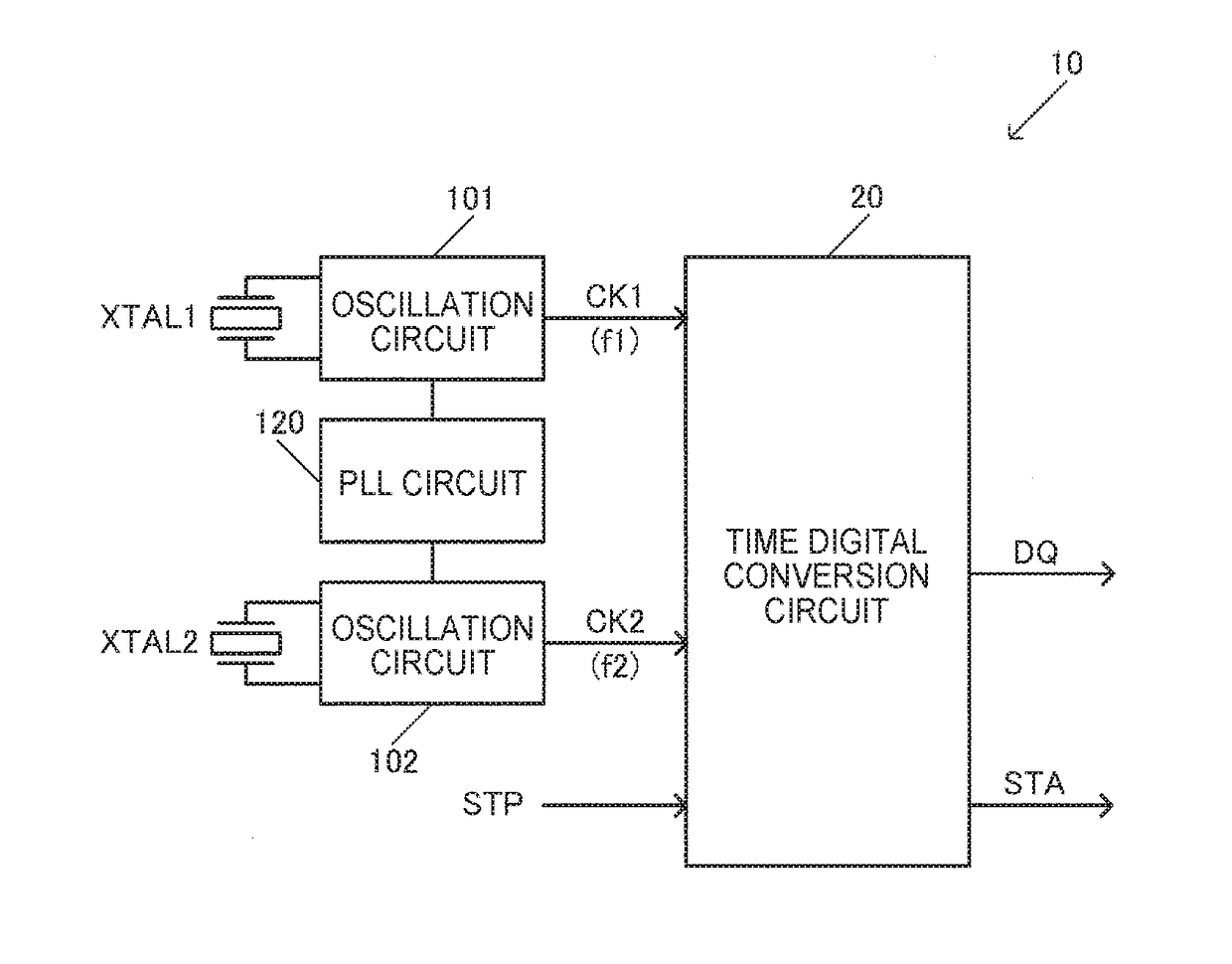
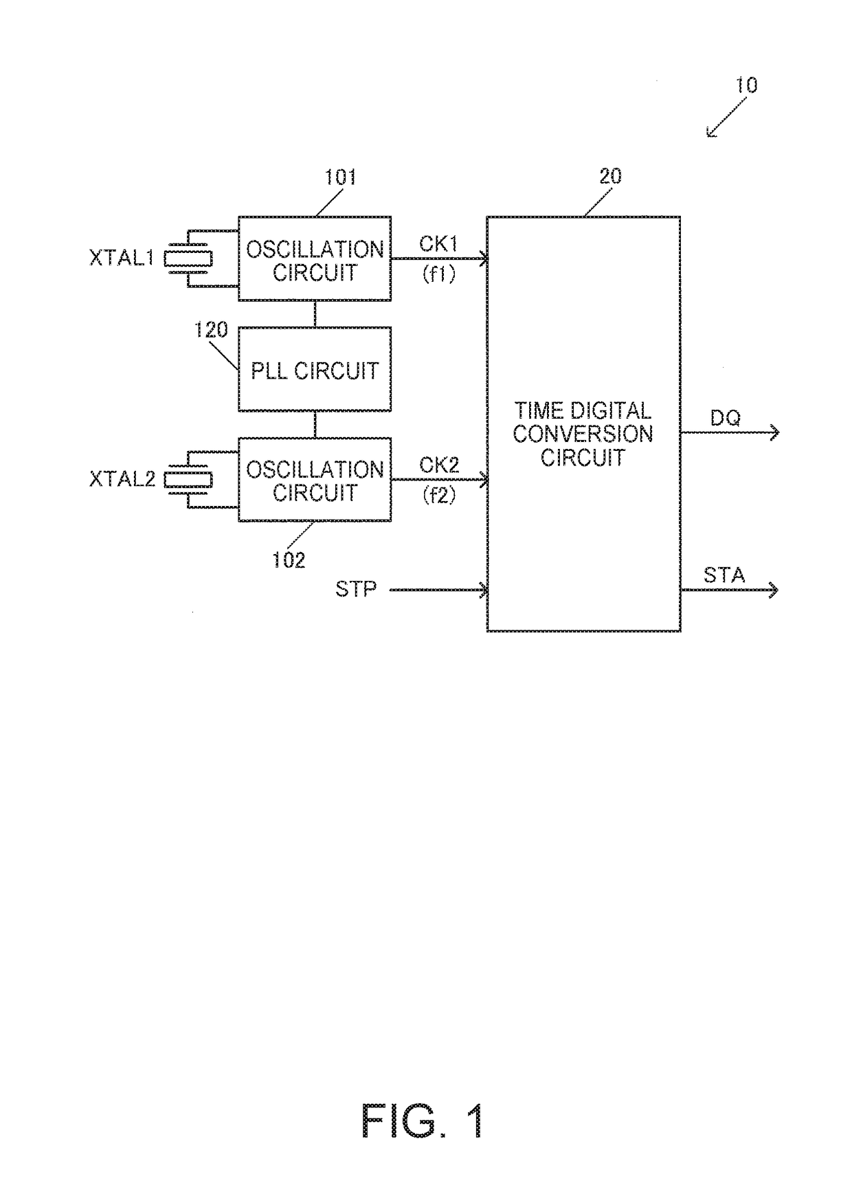
[0058]FIG. 1 shows a configuration example of a circuit device 10 according to the present embodiment. The circuit device 10 includes a time-to-digital conversion circuit 20, and a PLL circuit 120. Further, the circuit device 10 can include oscillation circuits 101, 102. It should be noted that the configuration of the circuit device is not limited to the configuration shown in FIG. 1, but a variety of practical modifications such as elimination of some of the constituents (e.g., the oscillation circuits) or addition of other constituents are possible.

[0059]The time-to-digital conversion ...


PUM


Abstract

A circuit device includes a time-to-digital conversion circuit, to which a first clock signal generated using a first resonator, and having a first clock frequency, and a second clock signal generated using a second resonator, and having a second clock frequency different from the first clock frequency are input, and which converts time into a digital value using the first and second clock signals, and a PLL circuit adapted to perform phase synchronization between the first and second clock signals.

Description

BACKGROUND1. Technical Field[0001]The present invention relates to a circuit device, a physical quantity measurement device, an electronic apparatus, a vehicle, and so on.2. Related Art[0002]In the past, there has been known a circuit device having a time-to-digital conversion circuit. The time-to-digital conversion circuit converts time into a digital value. As related art examples of a circuit device having such a time-to-digital conversion circuit, there are known related art technologies disclosed in, for example, JP-A-2009-246484 (Document 1), JP-A-2007-110370 (Document 2), JP-A-2010-119077 (Document 3) and JP-A-5-87954 (Document 4).[0003]In the related art technologies of Documents 1 through 3, the time-to-digital conversion is realized using a so-called vernier delay circuit. In the vernier delay circuit, the time-to-digital conversion is realized using delay elements as semiconductor elements.[0004]In Document 4, there is disclosed a minute time measurement device provided w...

Claims


Application Information

Patent Timeline
Patent Type & Authority Applications(United States)
IPC IPC(8): G04F10/00H03L7/093H03L7/099
CPCG04F10/005H03L7/093H03L7/0992B60L2200/00H03L7/18H03L7/181
Inventor KURASHINA, TAKASHIMAKI, KATSUHIKO
Owner SEIKO EPSON CORP
Learn More