Chromatic confocal distance sensor

a confocal distance sensor and chromatic technology, applied in the field of chromatic confocal distance sensors, can solve the problems that the measurement accuracy cannot be significantly impaired, and achieve the effect of improving the measurement accuracy, reducing the requirement for the precision of the coupling of the objective to the rest of the housing, and reducing the required installation spa

Active Publication Date: 2018-04-05
PRECITEC OPTRONIK GMBH
View PDF26 Cites 4 Cited by
  • Summary
  • Abstract
  • Description
  • Claims
  • Application Information

AI Technical Summary

Benefits of technology

[0017]An additional carrier element, on which the beam splitter and the diaphragms are fastened, may be omitted if the beam splitter is configured as a beam splitter cube. Then, the prisms of which the beam splitter cube consists themselves form a carrier which ensures the desired distance of the diaphragms from the beam splitter surface. The diaphragms are then carried directly by outer surfaces of the two prisms. To this end, the relevant outer surfaces of the prisms, apart from the diaphragm opening, may be coated so as to be absorbent or reflecting. It is favorable for the measurement light to strike the beam splitter surface as a divergent ray bundle, because in this way less stray light enters the spectrometer and the measurement accuracy is improved, at least for measurement objects which reflect only little measurement light because of a low reflection coefficient or an oblique object surface.
[0018]Preferably, the imaging optics comprise an objective, which is fastened replaceably on a part of the housing, the measurement light coming from the direction of the light source entering the objective as a collimated ray bundle. A replaceable objective makes it possible to use objectives with different focal lengths and therefore to adapt the measurement distance to the specific measurement task. Since the measurement light coming from the beam splitter as a collimated ray bundle enters the objective, the requirements for the precision of the coupling of the objective to the rest of the housing are reduced.
[0019]In one exemplary embodiment, the spectrometer contains a detector line, a reflective diffraction grating, and spectrometer optics which image the second diaphragm onto the detector line. The spectrometer optics are arranged in the light path of the measurement light in such a way that the measurement light passes through them before and after reflection at the diffraction grating. Because of this double pass through the spectrometer optics, the required installation space can be reduced further. Nevertheless, it is possible to use high-quality spectrometer optics consisting of a plurality of lenses, which image the second diaphragm sharply onto the detector line and therefore ensure high signal strengths.
[0020]Preferably, the housing comprises an automatic changeable coupling, with which the housing can be fastened automatically on a holder of a coordinate measuring machine. The advantages of the very small and lightweight distance sensor can then be employed for use in a coordinate measuring machine. The small and lightweight distance sensor may also, independently of coordinate measuring machines, advantageously be used for all measurement tasks in which a small size and a low weight of the distance sensor are important.

Problems solved by technology

Since the thermal dissipation is problematic for such densely packed optical elements, the first diaphragm and the second diaphragm are fastened together on a carrier which has an isotropic thermal expansion coefficient.
Consequently, in the event of temperature changes, which are not fully avoidable because of the compact design, a significant impairment of the measurement accuracy can no longer take place.

Method used


Image

  • Chromatic confocal distance sensor
  • Chromatic confocal distance sensor
  • Chromatic confocal distance sensor

Examples


Embodiment Construction

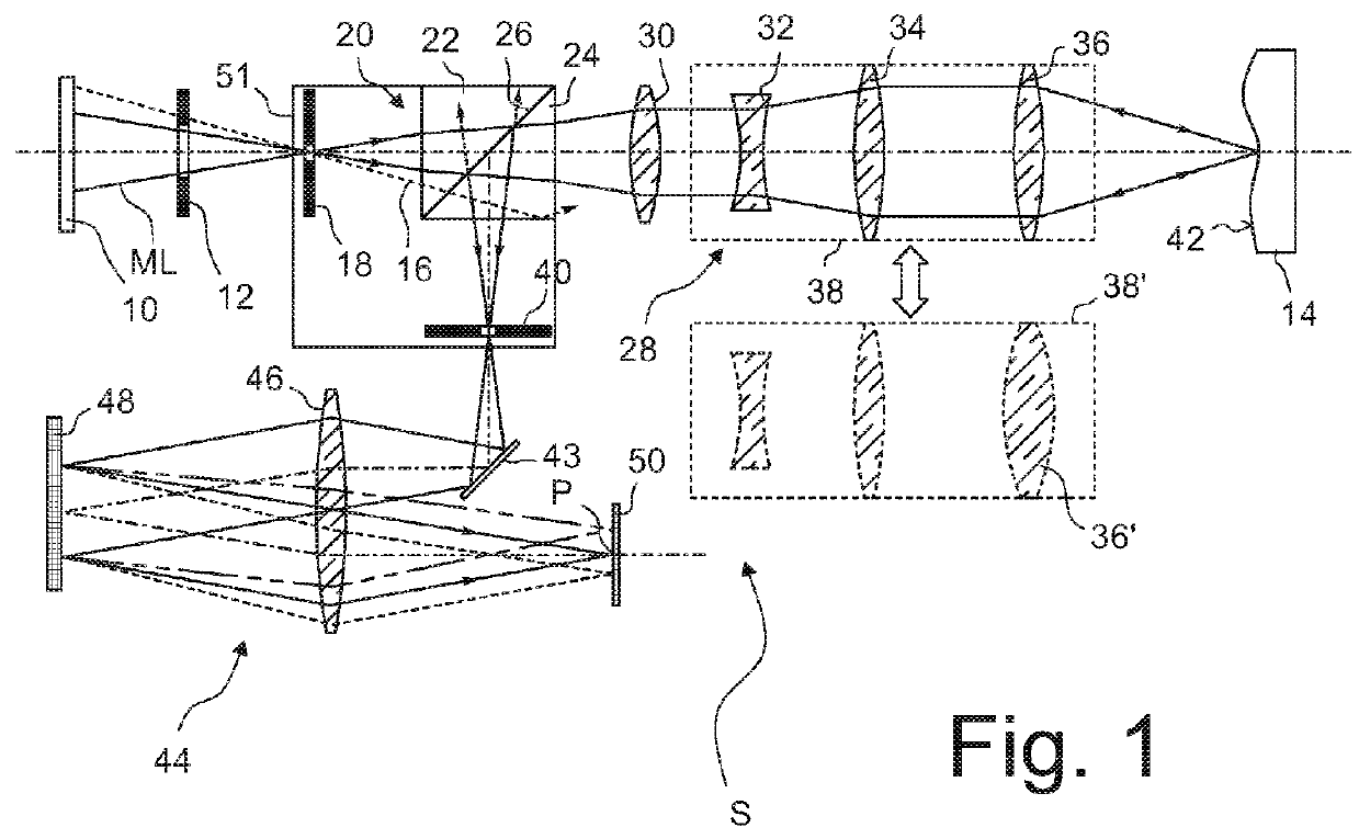
[0029]FIG. 1 shows, in a simplified meridional section, the beam path of a distance sensor according to the invention, denoted overall by S, according to a first exemplary embodiment. At the top left in FIG. 1, the number 10 denotes a light source which is configured in order to generate polychromatic measurement light ML. Polychromatic refers to light which is not monochromatic and therefore does not consist only of light of a single wavelength. The spectrum of the polychromatic measurement light ML may be continuous or discrete.

[0030]In the exemplary embodiment represented, the light source 10 used is a white light LED to generate a continuous spectrum between about 400 nm and 720 nm. The white light LED emits the measurement light ML uniformly over its entire planar light exit surface.

[0031]The white light LED may be mounted on a special thermal bridge which dissipates the heat loss from the rear side of the LED to an adjacent housing wall.

[0032]Arranged behind tight source 10 in...


PUM


Abstract

A chromatic confocal distance sensor has a housing in which a polychromatic light source, imaging optics having a longitudinal chromatic aberration, a spectrometer and a planar beam splitter surface are arranged. These lie in the light path of the measurement light between the light source and the imaging optics and between the imaging optics and the spectrometer. A first diaphragm is arranged in the light path between the light source and the beam splitter surface, and a second diaphragm is arranged in the light path between the beam splitter surface and the spectrometer. The diaphragms are arranged mirror-symmetrically with respect to the beam splitter surface. The measurement light propagates as a free beam inside the housing. The beam splitter surface, the first diaphragm and the second diaphragm are fastened together on a carrier which has an isotropic thermal expansion coefficient. This way, temperature changes cannot significantly affect the measurement accuracy.

Description

BACKGROUND OF THE INVENTION1. Field of the Invention[0001]The invention relates to a chromatic confocal distance sensor, in which the light source, the imaging optics and the spectrometer are arranged in the same housing. With corresponding miniaturization of the individual modules, such a distance sensor can have dimensions so small, and be so lightweight, that it can be fastened on a holder of a coordinate measuring machine (CMM).2. Description of the Prior Art[0002]Chromatic confocal distance sensors have been used for many years in industrial metrology when distances to object surfaces need to be measured contactlessly and with high accuracy. In the case of transparent objects, it is also possible to measure wall thicknesses or other thicknesses since, in general, it is possible to measure a distance for each optical interface and the thickness is obtained as the difference between the measured distances.[0003]Chromatic confocal distance sensors contain a light source, which gen...

Claims


Application Information

Patent Timeline
Patent Type & Authority Applications(United States)
IPC IPC(8): G01J3/02G01B11/00
CPCG01J3/0256G01J3/0286G01B11/005G01J3/0291G01J3/0202G01B11/026G01B2210/50
Inventor MARSAUT, DAVIDSCHONLEBER, MARTIN
Owner PRECITEC OPTRONIK GMBH
Why Eureka
Try Eureka