Variable-frequency magnetoresistive effect element and oscillator, detector, and filter using the same

a technology of variable frequency magnetoresistive effect and element, which is applied in the direction of magnetic bodies, instruments, substrate/intermediate layer, etc., can solve the problems of increasing the operation energy of the elements and not being suitable for use in devices, so as to and reduce the energy consumption of the device

Active Publication Date: 2018-04-12
TDK CORPARATION
View PDF0 Cites 6 Cited by
  • Summary
  • Abstract
  • Description
  • Claims
  • Application Information

AI Technical Summary

Benefits of technology

[0008]According to the above features of the aspect of the present invention, a spin torque oscillation effect can be caused in the magnetoresistive effect element in response to inputting of a DC signal to the magnetoresistive effect element from the input signal line. Owing to the spin torque oscillation effect, the magnetoresistive effect element is able to output an AC signal from the output signal line. Alternatively, a spin torque resonance effect can be caused in the magnetoresistive effect element in response to inputting of an AC signal to the magnetoresistive effect element from the input signal line. Owing to the spin torque resonance effect, an AC signal having a frequency equal to the spin torque resonance frequency of the magnetoresistive effect element in the input AC can be converted into a DC signal. Alternatively, owing to the spin torque resonance effect, element impedance can be reduced for an AC signal having a frequency equal to the spin torque resonance frequency of the magnetoresistive effect element in the input AC signal. The variable-frequency magnetoresistive effect element according to the aspect of the present invention is capable of varying oscillation frequency or resonance frequency of the magnetoresistive effect element by simultaneously applying a magnetic field and an electric field if necessary. At that time, the variable-frequency magnetoresistive effect element is capable of continuously controlling the oscillation frequency or the resonance frequency by varying the voltage applied via the control terminal or polarity of the applied voltage. Further, the variable-frequency magnetoresistive effect element is capable of maintaining the resulting state even after the electric field and the magnetic field are removed. As a result, the variable-frequency magnetoresistive effect element according to the aspect of the present invention is able to greatly reduce energy consumption of devices compared with the scheme in which the frequency is continuously varied by using a magnetic field. In addition, the variable-frequency magnetoresistive effect element according to the aspect of the present invention is capable of maintaining the resulting state without continuously applying a predetermined electric field compared with the scheme in which the frequency is continuously varied by using an electric field. Therefore, the variable-frequency magnetoresistive effect element according to the aspect of the present invention is able to implement frequency control with stabilized frequency fluctuation and less energy consumption.
[0037]According to aspects of the present invention, a variable-frequency magnetoresistive effect element capable of greatly reducing operation energy used for frequency control and of maintaining the resulting frequency can be provided. In addition, an energy-efficient variable-frequency oscillator, detector, and filter using such a variable-frequency magnetoresistive effect element can be provided.

Problems solved by technology

However, according to an examination made by the inventor, these variable-frequency means of the related art have an issue in that they are desired to stably maintain the applied magnetic field or electric field without any fluctuation during a frequency control operation and are thus not suitable for use in devices.
This consequently causes an issue of greatly increased operation energy of the elements.

Method used


Image

  • Variable-frequency magnetoresistive effect element and oscillator, detector, and filter using the same
  • Variable-frequency magnetoresistive effect element and oscillator, detector, and filter using the same
  • Variable-frequency magnetoresistive effect element and oscillator, detector, and filter using the same

Examples


first embodiment

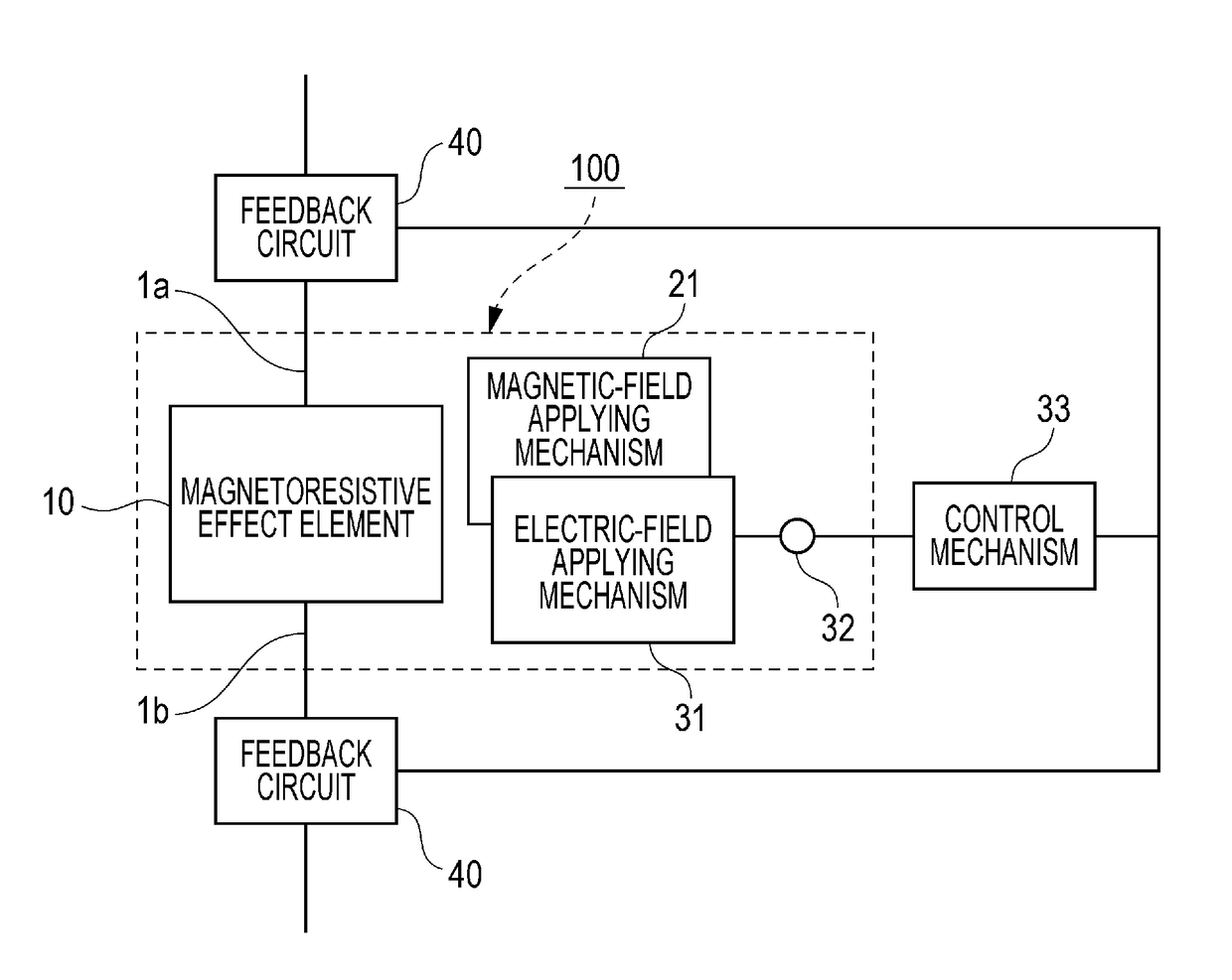
[0058]FIG. 1 is a schematic diagram illustrating a configuration of a variable-frequency magnetoresistive effect element 100 according to a first embodiment of the present invention. The variable-frequency magnetoresistive effect element 100 includes a magnetoresistive effect element 10, a magnetic-field applying mechanism 21, an electric-field applying mechanism 31, and a control terminal 32. An input signal line 1a and an output signal line 1b are connected to the magnetoresistive effect element 10. The input signal line 1a and the output signal line 1b respectively allow an input signal and an output signal to flow therethrough. The control terminal 32 is connected to the electric-field applying mechanism 31. By applying a positive or negative voltage to the electric-field applying mechanism 31 via the control terminal 32, an electric field having a predetermined magnitude and a predetermined direction can be applied to the magnetoresistive effect element 10 via the electric-fiel...

second embodiment

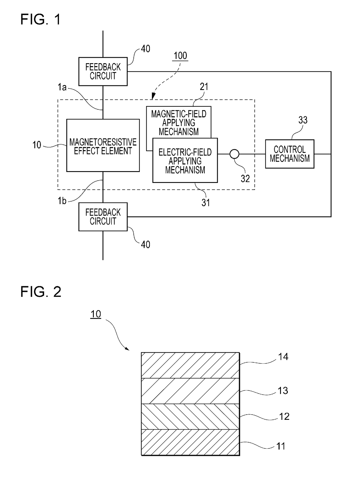
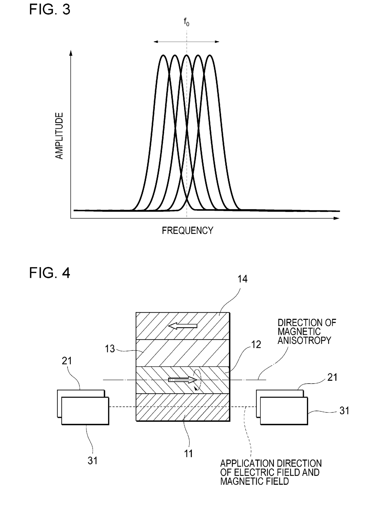
[0092]FIG. 4 is a schematic diagram illustrating a positional relationship among the magnetoresistive effect element 10, the magnetic-field applying mechanism 21, and the electric-field applying mechanism 31 in accordance with a second embodiment of the present invention. The magnetoresistive effect element 10 includes the control layer 11, the magnetization free layer 12 in which the direction of magnetization is variable, the intermediate layer 13, and the magnetization fixed layer 14 in which the direction of magnetization is fixed. The magnetization fixed layer 14 is composed of a ferromagnetic material, and the magnetization direction of the magnetization fixed layer 14 is substantially fixed to one in-plane direction of the magnetization fixed layer 14. The magnetic-field applying mechanism 21 has a function of applying a magnetic field to the control layer 11 in a direction perpendicular to the stacking direction. The electric-field applying mechanism 31 has a function of app...

third embodiment

[0096]FIG. 5 is a schematic diagram illustrating a positional relationship among the magnetoresistive effect element 10, the magnetic-field applying mechanism 21, and the electric-field applying mechanism 31 in accordance with a third embodiment of the present invention. The magnetoresistive effect element 10 includes the control layer 11, the magnetization free layer 12 in which the direction of magnetization is variable, the intermediate layer 13, and the magnetization fixed layer 14 in which the direction of magnetization is fixed. The magnetization fixed layer 14 is composed of a ferromagnetic material, and the magnetization direction of the magnetization fixed layer 14 is substantially fixed to one in-plane direction of the magnetization fixed layer 14. The magnetic-field applying mechanism 21 has a function of applying a magnetic field to the control layer 11 in a direction perpendicular to an in-plane direction of the control layer 11. The electric-field applying mechanism 31...


PUM

PropertyMeasurementUnit
thicknessaaaaaaaaaa
thicknessaaaaaaaaaa
thicknessaaaaaaaaaa

Abstract

A variable-frequency magnetoresistive effect element includes a magnetoresistive effect element, a magnetic-field applying mechanism that applies a magnetic field to the magnetoresistive effect element, an electric-field applying mechanism that applies an electric field to the magnetoresistive effect element, and a control terminal connected to the electric-field applying mechanism and used for applying a voltage that varies in at least one of magnitude and polarity to the electric-field applying mechanism. The magnetoresistive effect element contains an antiferromagnetic material or ferrimagnetic material having a magnetoelectric effect. A spin torque oscillation frequency or spin torque resonance frequency of the magnetoresistive effect element is controlled by varying the voltage applied via the control terminal in at least one of magnitude and polarity.

Description

BACKGROUND OF THE INVENTION1. Field of the Invention[0001]The present invention relates to an variable-frequency magnetoresistive effect element that uses the magnetoresistive effect and can be utilized in devices necessary for wireless communication such as an oscillator, a detector, and a filter.2. Description of the Related Art[0002]With the decreasing size and enhanced functionality of mobile terminals such as smartphones, the number of electronic components used in such mobile terminals and a space assigned to such electronic components are tending to decrease. In addition, due to the increasing communication speed and increasing variety of applications, the number of frequencies or frequency bands to be used is tending to increase. To meet these trends, there is a strong demand for multiband high-frequency components capable of controlling a plurality of frequency bands by themselves.[0003]Oscillation (or resonance) elements that use the magnetoresistive effect are notably sma...

Claims


Application Information

Patent Timeline
Patent Type & Authority Applications(United States)
IPC IPC(8): H01L43/08H01L43/02H01L43/10H03B15/00H03H11/04H01F10/00H01F10/32H01F1/147G01R33/09
CPCH01L43/08H01L43/02H01L43/10H03B15/006H03H11/04H01F10/002H01F10/3218H01F1/147G01R33/09H10N50/10G01R33/093G01R33/098H03H2/00H03H2/001H01F10/3286H01F10/329H10N50/80H10N50/85
Inventor SHIBATA, TATSUO
Owner TDK CORPARATION
Why Eureka
Try Eureka