Battery pack

a battery pack and battery technology, applied in the field of batteries, can solve the problems of difficult to absorb heat equally from the respective batteries, the air blown out of the fan device may not reach near every single battery, and the effect of reducing the number of batteries is not easy to achieve, so as to achieve reliable heat dissipation, reduce the number of batteries, and improve the strength of the housing

Active Publication Date: 2018-04-12
DENSO CORP
View PDF3 Cites 22 Cited by
  • Summary
  • Abstract
  • Description
  • Claims
  • Application Information

AI Technical Summary

Benefits of technology

[0009]According to the configuration as above, the circulation passage is formed to let a fluid flowing through the first fluid passage flow into the second fluid passage by flowing through the battery passage. Hence, a fluid flowing out from the fluid drive member can be prevented from flowing into the second fluid passage before passing through the first fluid passage. Accordingly, fluid flowing out from the fluid drive member sequentially flows the first fluid passage and the battery passage and flows back into the fluid drive member by flowing the second fluid passage. The configuration as above enables a fluid carrying heat absorbed from the cells while flowing through the battery passage to dissipate the heat to the outside of the housing when flowing the first fluid passage. Consequently, reliable heat dissipation via the housing can be achieved.
[0010]In addition, the multiple beams are provided on the bottom wall. Hence, the respective beams function as reinforcing members and strength of the housing can be increased. The multiple cells are located on the respective beams. Hence, should an impact be applied from the outside of the housing, the impact can be received by the respective beams. Consequently, a battery pack capable of realizing efficient heat dissipation from the housing and protecting the batteries against an impact can be provided.

Problems solved by technology

Hence, air blown out from the fan device may fail to reach near every single battery and the entire air may return to the fan device by taking a shortcut.
In such a case, it is difficult to absorb heat equally from the respective batteries by forcing circulating air to flow around every single battery.
Hence, effective heat dissipation via a housing wall may not be achieved.
In addition, the battery pack of Patent Literature 1 does not have a structure to make the housing of the battery pack more rigid.
Hence, the housing may not be strong enough to protect the battery cells against an impact applied to the battery pack for some reason.
In particular, a battery pack mounted to a vehicle has a potential risk of an impact in the event of a collision and requires a structure to protect the battery cells against an impact.

Method used


Image

  • Battery pack
  • Battery pack
  • Battery pack

Examples


first embodiment

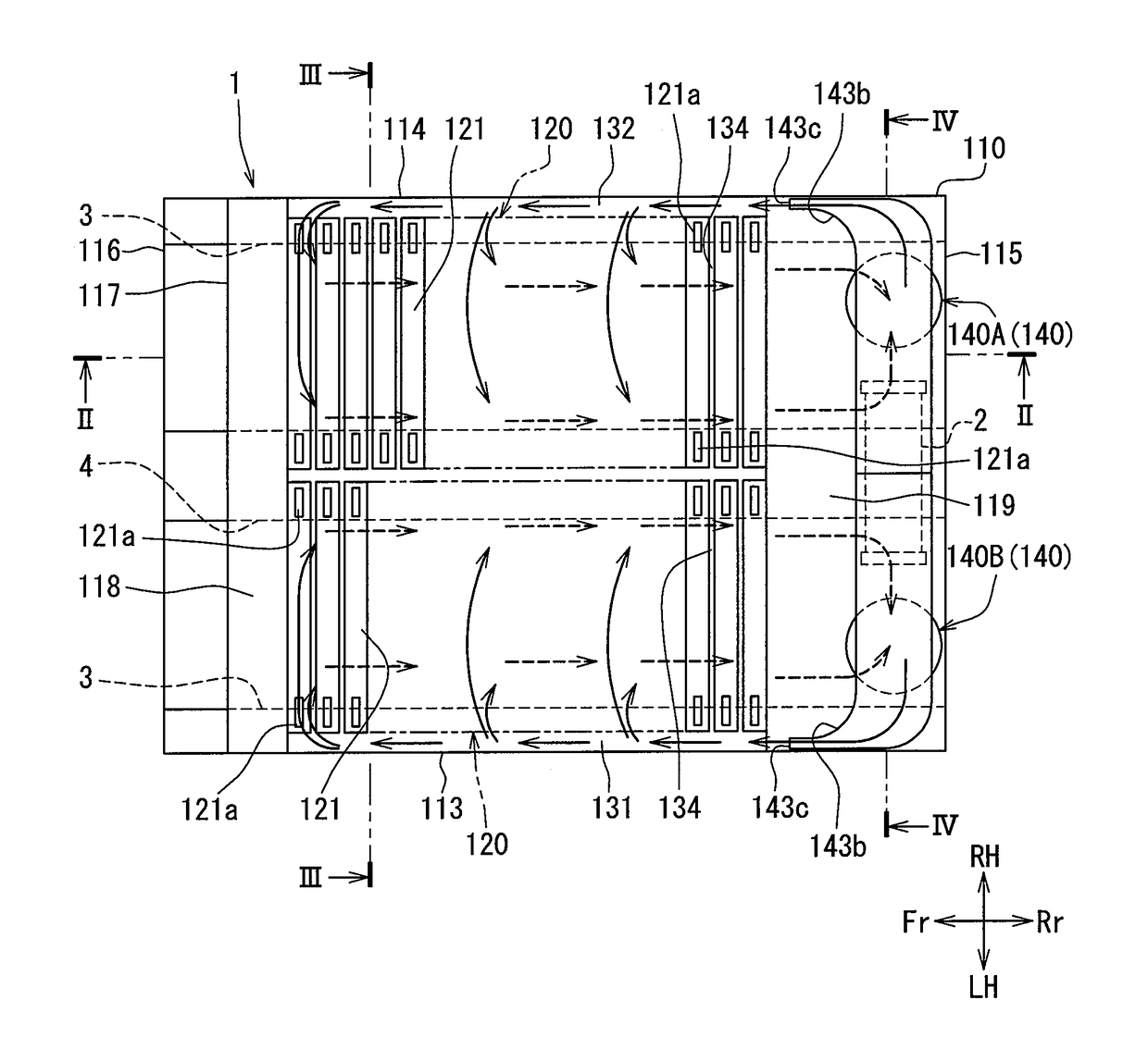
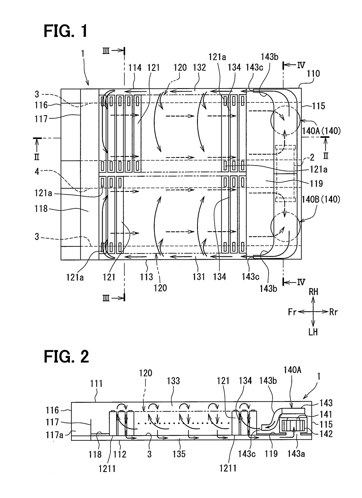
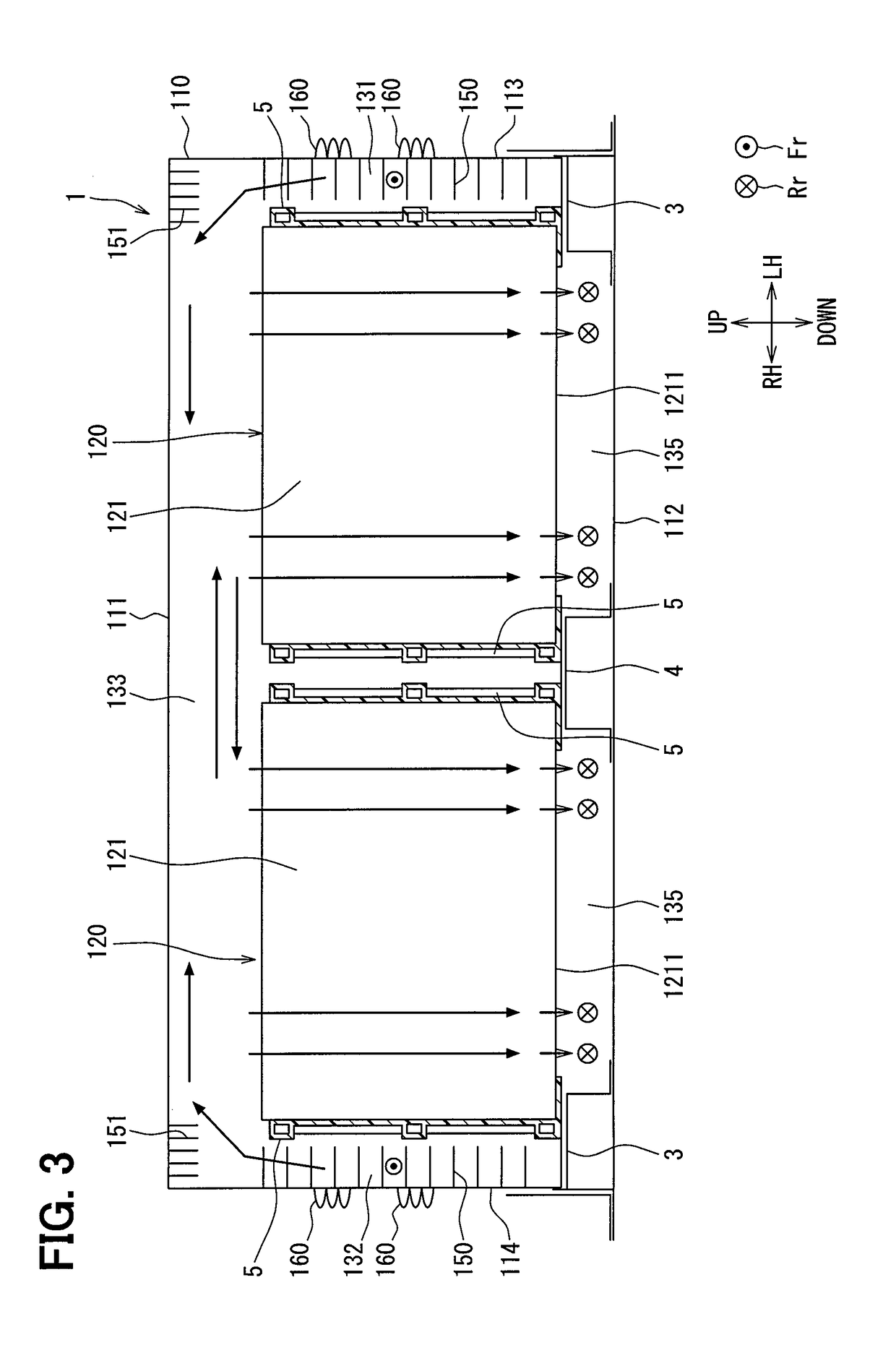
[0029]A battery pack 1 of a first embodiment will be described with reference to FIG. 1 through FIG. 14. The battery pack 1 is employed in, for example, a hybrid automobile run by both a motor driven on electrical power charged to a battery and an internal combustion engine as a drive source, or an electric automobile run by a motor as a drive source. Multiple cells 121 included in the battery pack 1 are, for example, nickel metal hydride batteries, lithium-ion rechargeable batteries, or organic radical batteries.

[0030]The battery pack 1 is installed to a pack storing space, such as a trunk room of a vehicle or an area on a back of the trunk room provided below the trunk room. Alternatively, the pack storing space may be a space where, for example, a spare tire, tools, and so on can be also stored. The battery pack 1 is installed in the battery pack storing space in a posture with a bottom wall 112 and a bottom wall passage 135 on an underside.

[0031]The battery pack 1 may be install...

second embodiment

[0111]A second embodiment will describe a battery pack 101 with reference to FIG. 15 through FIG. 17. The battery pack 101 is a modification of the battery pack 1 of the first embodiment above. In FIG. 15 through FIG. 17, components labelled with same reference numerals used in the drawings referred to in the first embodiment above are same components and exert same functional effects. The following will describe a content different from the first embodiment above.

[0112]In contrast to the battery pack 1, the battery pack 101 includes a communication passage 8 via which the bottom wall passages 135 respectively corresponding to two battery assemblies aligned side by side in a right-left direction communicate with each other.

[0113]As is shown in FIG. 15, an inner space surrounded by an inner surface of a second beam 104 and a bottom wall 112 defines the communication passage 8 connecting the bottom wall passage 135 on a vehicle left side as one side and the bottom wall passage 135 on ...


PUM

PropertyMeasurementUnit
convection currentsaaaaaaaaaa
heataaaaaaaaaa
structureaaaaaaaaaa

Abstract

A battery pack includes: a battery assembly including a plurality of batteries; a fluid drive member driving a fluid which cools the battery assembly; a housing that houses the battery assembly and the fluid drive member; and a beam provided integrally with a bottom wall of the housing to support the battery assembly from a lower side. A circulation passage provided in the housing includes: a first fluid passage between the battery assembly and a side wall of the housing; a battery passage between the batteries; and a second fluid passage downstream of the battery passage and extending toward the fluid drive member. The second fluid passage is surrounded by at least the beams, the bottom wall, and a lower end of the battery assembly.

Description

CROSS REFERENCE TO RELATED APPLICATION[0001]This application is based on Japanese Patent Application No. 2015-157257 filed on Aug. 7, 2015, the disclosure of which is incorporated herein by reference.TECHNICAL FIELD[0002]The present disclosure relates to a battery pack having battery cells housed in a casing.BACKGROUND ART[0003]A battery pack housing battery cells is described in Patent Literature 1. The battery pack of Patent Literature 1 includes multiple batteries and a fan device developing convection currents in a housing mounted to an automobile. In the battery pack, multiple cells are cooled with air blown out from the fan device by letting the air circulate in the housing while developing convection currents such that make contact with the batteries in the housing.PRIOR ART LITERATURESPatent Literature[0004]Patent Literature 1: JP 2009-211829 ASUMMARY OF INVENTION[0005]In the battery pack of Patent Literature 1, a circulation passage in which air flows out from an outlet por...

Claims


Application Information

Patent Timeline
Patent Type & Authority Applications(United States)
IPC IPC(8): H01M10/6556H01M2/10H01M10/625H01M10/613H01M10/6563H01M50/209H01M50/289
CPCH01M10/6556H01M2/1077H01M10/625H01M10/613H01M10/6563H01M2220/20H01M10/647H01M10/6555Y02E60/10H01M50/209H01M50/289
Inventor YAMAMOTO, HIROYOSHIINOUE, YOSHIMITSUYAMASHITA, KOJIIGUCHI, SHOTA
Owner DENSO CORP
Why Eureka
Try Eureka