Surge suppressor

a technology of surge suppressor and suppressor body, which is applied in the direction of overvoltage protection resistor, overvoltage protection arrangement for emergency protection of excess voltage/current, spark gap details, etc., can solve the problem of increasing arc voltage, and achieve the effect of preventing the thermal destruction of the overvoltage-limiting componen

Inactive Publication Date: 2018-04-12
PHOENIX CONTACT GMBH & CO KG
View PDF5 Cites 2 Cited by
  • Summary
  • Abstract
  • Description
  • Claims
  • Application Information

AI Technical Summary

Benefits of technology

[0008]Therefore, the object of this invention is to make available the above described surge suppressor in which reliable disconnection of

Problems solved by technology

Thus, a guided discharge of plasma out of the region between the contacts which has been caused by the

Method used


Image

  • Surge suppressor
  • Surge suppressor
  • Surge suppressor

Examples


Embodiment Construction

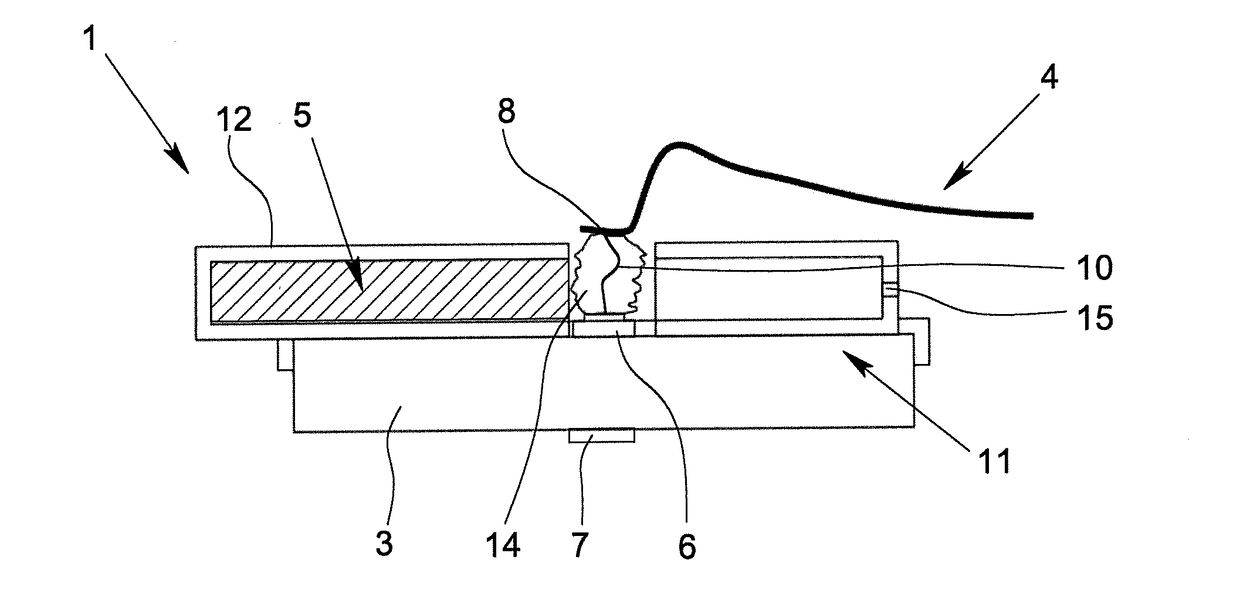
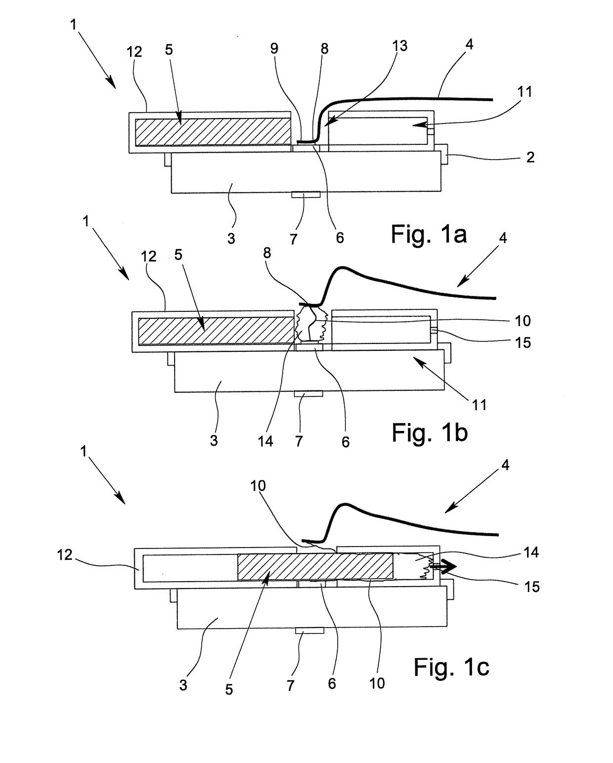
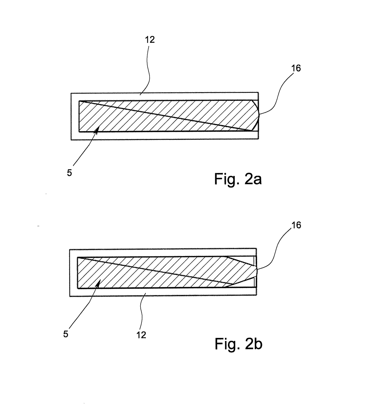
[0054]The figures show schematics of different exemplary embodiments of a surge suppressor 1 with a housing 2 which is shown only partially in the figures and in which there is a varistor 3 as the overvoltage-limiting component. Moreover, the surge suppressor 1 has another electrically conductive connecting element 4 and at least one isolating interrupter 5, of which different versions are shown in FIGS. 2a to 4b.

[0055]The varistor 3 has a first terminal 6 and a second terminal 7 which are connected in an electrically conductive manner to the terminal contacts of the surge suppressor 1 which are not shown here, when the surge suppressor 1 is in the normal state, i.e., is not disconnected. In the normal state of the surge suppressor 1 which is shown in FIG. 1a, the first terminal 6 of the varistor 3 is connected to the first end 8 of the electrically conductive connecting element 4 via a thermally breaking connection. In the exemplary embodiments shown, the thermally breaking connec...


PUM


Abstract

A surge suppressor with a housing, a varistor located in the housing, an electrically conductive connecting element and at least one isolating interrupter. The isolating interrupter is movable relative to a first terminal of the varistor out of a first position into a second position, in the normal state of the surge suppressor, a first end of the electrically conductive connecting element being connected to the first terminal of the varistor in an electrically conductive manner and the isolating interrupter being held in its first position. When a critical state of the varistor is reached, the isolating interrupter is moved into its second position in which a segment of the interrupter is located between the first end of the electrically conductive connecting element and the first terminal. Reliable disconnection from the power system is ensured by the arc formed being moved into at least one partially closed chamber.

Description

BACKGROUND OF THE INVENTIONField of the Invention[0001]The invention relates to surge suppressor with a housing, with an overvoltage-limiting component located in the housing, with an electrically conductive connecting element and with at least one isolating interrupter, the overvoltage-limiting component having a first terminal and a second terminal and the isolating interrupter being located to be able to move relative to the first terminal of the overvoltage-limiting component so that it can be moved out of a first position into a second position.Description of Related Art[0002]Overvoltage protection is defined as the protection of electrical and electronic devices against overly high electrical voltages. The required measures for protection of systems and devices are divided into different stages according to the overvoltages which are to be expected. The protective gear for the individual stages differs in particular by the level of the discharge capacity and the protection lev...

Claims


Application Information

Patent Timeline
IPC IPC(8): H02H3/20
CPCH02H3/20H01C7/12H01H9/32H01H37/74H01T1/02H01T1/14H01C7/126H02H9/042H01H85/36
Inventor SCHMUTZ, JAN-ERIKHEGERFELD, JANWETTER, MARTIN
Owner PHOENIX CONTACT GMBH & CO KG
Why Eureka
Try Eureka