
Impeller for a centrifugal headbox feed pump

Active Publication Date: 2018-04-26
SULZER MANAGEMENT AG
View PDF11 Cites 8 Cited by
  • Summary
  • Abstract
  • Description
  • Claims
  • Application Information

AI Technical Summary

Benefits of technology

The present invention is designed to address the requirements of both water-laid and foam-laid fibrous web making processes. The new centrifugal headbox feed pump has several advantages over traditional pumps, including being able to pump both water-based and foam-based stocks with low pulsation, high efficiency ratio, and a simple construction. The pump can also separate gas from the stock, reduce required suction head, lower energy consumption, and lower costs. Additionally, the pump has more flexibility in installation and can be easily provided with means for preventing fiber collection and separating gas from the foam-based suspensions or stock.

Problems solved by technology

From the early times of papermaking the production rates of fibrous web machines have continuously increased such that the volume flows of the dilute suspensions introduced to fibrous web machines are now enormous.
However, as the efficiency ratio is inversely proportional to the distance, the distance is, in practice, nowadays, rather reduced than increased.
Again, practical reasons prevent increasing of the number of working vanes too high as the efficiency ratio will be compromised due to reducing open cross-sectional flow area and increasing friction in the vane passages.
However, the double suction pump has a complicated construction, as both the impeller and the casing of the pump are difficult, and costly, to manufacture.
When in use the double suction pumps have substantially poor efficiency ratios (of the order of 91%), at least when compared to pumps using end suction or single suction impellers.
The reasons for the reduction of the efficiency ratio relate to the complicated suction inlet construction, and the inclination of the working vanes, meaning increased surface area (friction) and narrower flow passages.
An additional downside in double suction pumps, especially at lower production rates (partial load), is the tendency of the pump to start switching the flow from one side of the impeller shroud to the opposite side thereof and back (cf. von Karman vortex), which means, in practice, that only one of the impeller sides is working at a time.
As to the efficiency ratio of the single end suction pump with partitioned impeller it is somewhat better than that of double suction pumps, but still the inclination of the working vanes, meaning increased surface area (friction) and narrower flow passages, reduces the efficiency.
However, the added partition wall makes the construction of the impeller complicated and costly to manufacture.
However, when the prior art impellers were studied in more detail, it was learned that there is still one more source of pulsation that has not been understood and thus not been taken into account when designing the prior art impellers.
A further additional challenge the manufacturers of fibrous webs sometimes set for the equipment producers to solve is their desire to be able to use both liquid-laid and foam-laid web-making stocks in their process.
The tendency is, in a way, far more severe than when pumping liquid based stocks due to generation of noise and heavy vibration, which might, at worst, cause cracks in the flow piping.
In paper or board machines used for producing some less demanding end products there has been no deculator in the approach flow system, but still the low consistency of the stock has ensured that the gas content of the stock has not been even close to causing problems in pumping.
Therefore, traditional headbox feed pumps have never been provided with any means for managing gas in the stock.
Furthermore, the additional requirement that the pump should be sometimes provided with gas separation results in that the construction of such pumps would get even more complicated.

Method used


Image

  • Impeller for a centrifugal headbox feed pump
  • Impeller for a centrifugal headbox feed pump
  • Impeller for a centrifugal headbox feed pump

Examples


Embodiment Construction

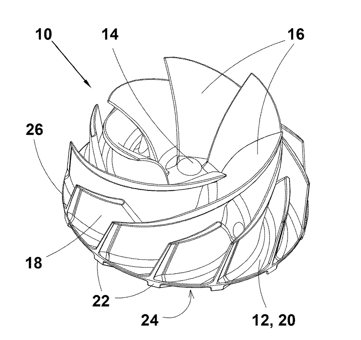
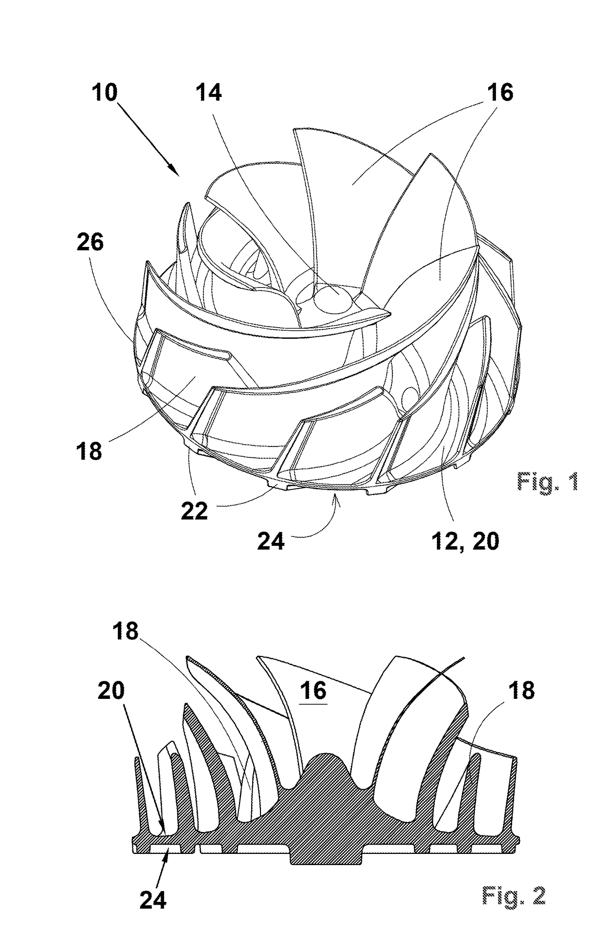
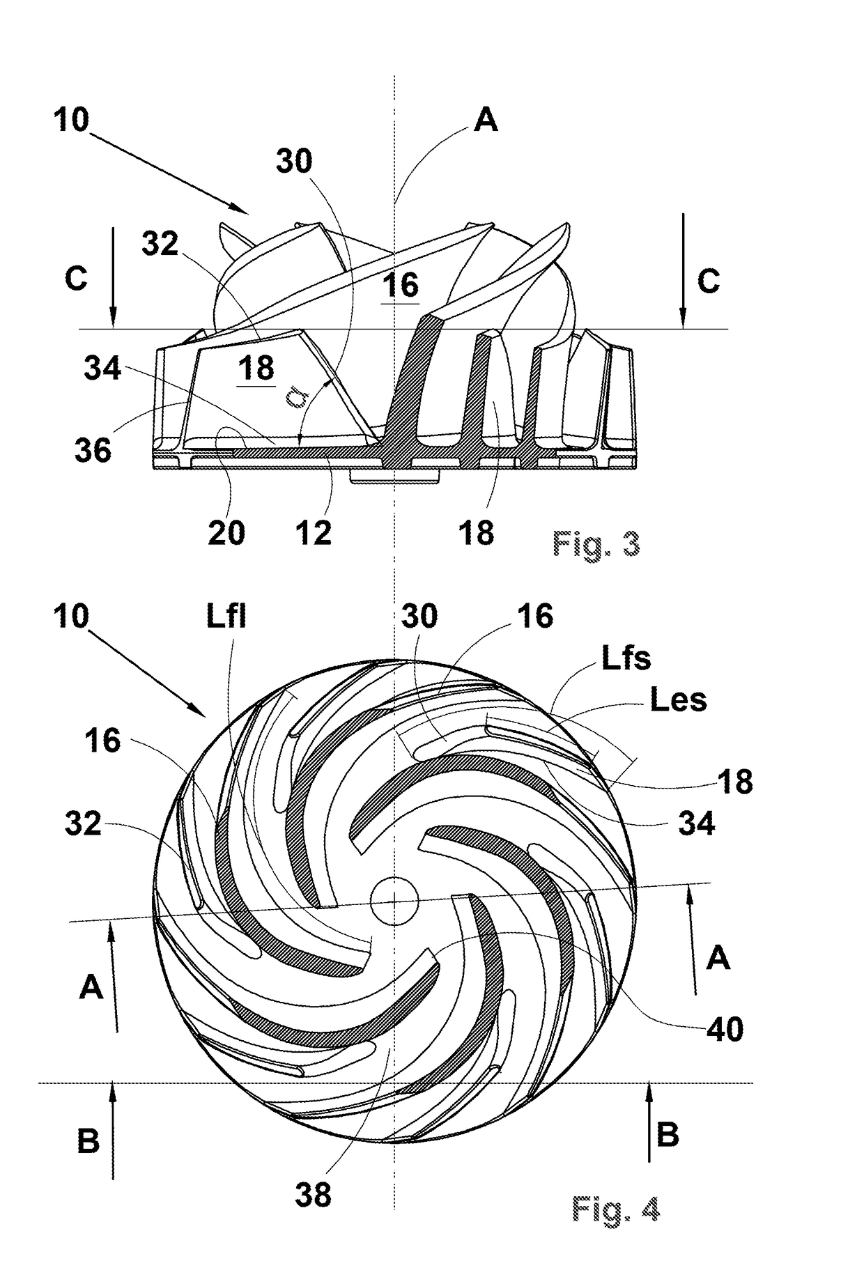
[0040]FIG. 1 illustrates a perspective view and FIG. 2 a cross-sectional view along line A-A of FIG. 4 of the impeller in accordance with a preferred embodiment of the present invention. The impeller 10 is a semi-open impeller having a rear plate or shroud 12 with a hub 14 and longer working vanes 16 and at least one intermediate or shorter working vane 18 in each vane passage between the longer working vanes 16 at the front side of the shroud 12, i.e. at the face 20 of the shroud 12 facing the pump inlet (not shown). The shroud 12 preferably, but not necessarily includes rear vanes 22 at the rear face 24 of the shroud 12. In a further variation of the present invention the rear face 24 includes as many rear vanes 22 as there are working vanes 16 and 18 on the front face 20 of the shroud, the rear vanes 22 being positioned opposite the working vanes 16 and 18 and having, preferably but not necessarily, the same length as the working vanes 16 and 18. The shroud 12 has an outer circum...


PUM


Abstract

An impeller structure for a centrifugal pump that can feed both fibrous suspensions and water into a headbox of a fibrous web machine. The centrifugal pump utilizing the impeller structure pumps stock for both liquid-laid and foam-laid paper, tissue or board making applications and pumps water or other dilution fluid into a headbox circulation. In general, the impeller of the present invention is especially suitable for all such pumping tasks in the production of fibrous webs that a pulseless or low-pulse impeller is needed.

Description

CROSS-REFERENCE TO RELATED APPLICATIONS[0001]This application is a U.S. National Stage application of International Application No. PCT / EP2015 / 081357, filed Dec. 29, 2015, which claims priority to European Patent Application No. 15163713.9, filed Apr. 15, 2015 the contents of each of which are hereby incorporated herein by reference.BACKGROUNDField of Invention[0002]The present invention relates to an impeller for a centrifugal pump. The present invention relates especially to a novel impeller structure for a centrifugal pump used for feeding both fibrous suspensions and water into a headbox of a fibrous web machine. The centrifugal pump utilizing the impeller of the present invention is, for instance, suitable for pumping fibrous suspensions, i.e. stock for liquid-laid paper, tissue or board making applications and for pumping water or other dilution fluid into the headbox circulation. In general, the impeller of the present invention is especially suitable for all such pumping tas...

Claims


Application Information

Patent Timeline
IPC IPC(8): F04D29/24F04D29/44
CPCF04D29/24F04D29/445F04D1/00F04D7/04F04D29/22F04D29/2261F04D29/242
Inventor MANNINEN, HEIKKIVESALA, REIJO
Owner SULZER MANAGEMENT AG
Learn More