Radiopaque Procedure Site Marker and Method for Intraoperative Medical Imaging

a radiopaque procedure and site marker technology, applied in the field of surgical instruments and methods, can solve the problems of no longer visible site marking to the surgeon's eye, and no longer visible site marking

Active Publication Date: 2018-05-03
TARGET TAPE
View PDF5 Cites 3 Cited by
  • Summary
  • Abstract
  • Description
  • Claims
  • Application Information

AI Technical Summary

Benefits of technology

[0027]The apparatus and method of the present and illustrated inventions are based on a device that defines an improved means and method of marking a patient requiring an endourologic procedure. As an example, an ureteroscopy procedure will be the sample endourologic procedure described henceforth. The aid is an adhesively-backed marker with a radiopaque marking symbol (“marker”) designed to eliminate risk of a WSS by creating a visible, unambiguous marking symbol on an intraoperative medical image. The marker is removably applied to the correct side of the patient's body on the groin or abdomen area before the patient is draped for surgery. The marker is visible to the naked eye before it is covered by drapes and visible on an X-ray whether covered by drapes or not. The visible marking symbol on the X-ray will be unambiguous and will communicate whether the procedure should or should not be performed on that location.
[0028]The marker must satisfy three primary constraints to achieve its purpose of producing a marking symbol on an intraoperative medical image while covered by drapes. These three constraints are: at least partially radiopaque marking symbol, unambiguous marking symbol, and attachment to the skin. Once these three constraints are met, additional features and benefits may be included to produce preferred embodiments that are user friendly and economical.
[0037]Accordingly, several objects and advantages of the invention are: to provide a visible and unambiguous marking symbol(s) on an X-ray image; to identify correct or incorrect procedure site(s); and prevent wrong site surgery in procedures that have traditional marks obscured by drapes. Other objects and advantages of the present invention, and / or of the currently preferred embodiments thereof, will become more readily apparent in view of the following detailed description of the currently preferred embodiments, other embodiments, and accompanying drawings.

Problems solved by technology

However, with the use of these marking pens, certain specific procedures can result in drapes covering the pen marking and therefore the site marking is no longer visible to the surgeon's eye.
Wrong site surgery (“WSS”) can be a devastating event with profound medical, legal, and social ramifications.
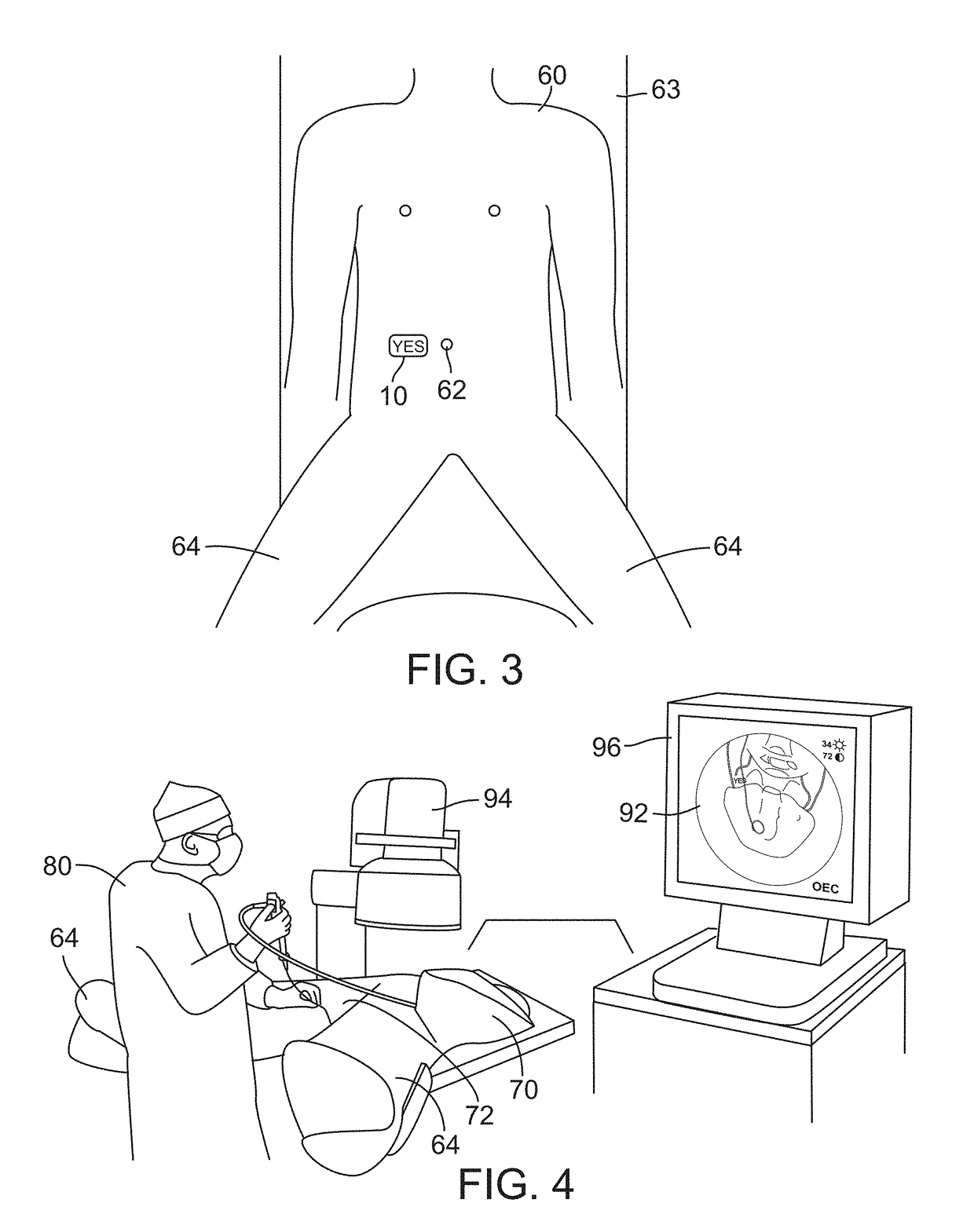
The problem with the universal protocol and its possible modifications a facility may incorporate, with respect to endourologic procedures, is that the site marking is no longer visible once the patient is draped; the site marking does not appear on the medical image; and a physician can become confused with the patient and / or medical image's orientation.
Draping defeats the purpose of marking the patient because the physician can no longer see the mark on the body.
However, the physician or technician may also inadvertently flip the displayed image.
Due to the relatively small image size, there may also be a lack of anatomic detail on fluoroscopy for orientation and to distinguish between the patient's left and right side.
Furthermore, as vision is often limited to what is on the image's video screen, others in the operating room do not have the ability to determine which side of the patient the procedure is being performed on.
Although a physician is trained to overcome orientation confusion, mistakes still occur as 20% of wrong site surgery is urologic.
The problem with this is that patient is no longer fully draped and part of their body that should be covered is now exposed.
Although this labels the patient's right and left side and helps with orienting the patient, this is an ambiguous technique because it does not label which is the correct site to operate on.
These labels also lack the ability to standardize a consistent marking system implemented by the physician or medical facility.
This can lead to confusion because some procedures will have different markings.
This is analogous to a map showing only the direction of North and relying on the user to identify remaining directions; while such marking may be sufficient on a map because everyone is familiar with compass rose directions it is ambiguous when it comes to patient marking and the physician does not have 100% clarity on the correct procedure side(s) with this method.
Having multiple meanings creates risk of error.
This ambiguity creates risk of a WSS.
The physician can interpret this as simply labeling which sides are the patient's left / right and each label does not necessarily validate that both sides require treatment.
Without a consistent method, there is no certainty that the physician will apply a sticker and recall with 100% certainty if the label means to perform the procedure over the respective marker, or if that marker only labels the patient's orientation.
Due to the “R” and “L” stickers not being readily available in departments compared to electrocardiography (ECG) tabs, the authors utilized SKINTACT ECG electrode tabs as a radiopaque marker.
Using a small pellet, although visible, is not the most user friendly.
It can be especially difficult if the pellet overlaps with a dense bone.
However, using homemade or non-standardized items creates the possibility of having a system that is not consistent and ambiguous among the medical facility and its staff members.
Having individuals perform various different techniques or using different radiopaque markers can create confusion and ultimately exposes the patient to risk of WSS.
None of the prior art addresses the problems and solutions of overcoming indelible marks that are covered by drapes using unambiguous techniques that can be consistent with a physician or medical facility's protocols in place.

Method used


Image

  • Radiopaque Procedure Site Marker and Method for Intraoperative Medical Imaging
  • Radiopaque Procedure Site Marker and Method for Intraoperative Medical Imaging
  • Radiopaque Procedure Site Marker and Method for Intraoperative Medical Imaging

Examples


Embodiment Construction

[0046]The invention will now be described with reference to the drawings. The embodiments disclosed herein are to be considered exemplary of the principles of the present invention and various equivalent modifications will be apparent to those skilled in the art based on the teachings herein without departing from the scope or spirit of the invention described in the specification or in the claims.

[0047]The term “marking symbol” is used herein to mean without limitation any desired graphic, character, alpha, numeric and / or alphanumeric combination and in any language that is suitable for use in a manner that would clearly indicate the correct or incorrect site of the surgical procedure. It should also be appreciated that any alpha, numeric, or alphanumeric image, phrase or term may further be configured in any desired font, including without limitation, such fonts as Times New Roman, Courier, Ariel and the like as well as in conjunction with any one or more special effect such as bo...


PUM


Abstract

An apparatus and method that provide an improved method of marking a patient requiring an endourologic procedure such as an ureteroscopy are disclosed. The apparatus is an adhesively-backed sheet with a radiopaque marking symbol designed to eliminate risk of a wrong site surgery by creating a visible, unambiguous marking symbol on an intraoperative medical image. The marker sheet is removably applied to the correct side of the patient's body on the groin or abdomen area before the patient is draped for surgery. The marker is visible to the naked eye before it is covered by drapes and visible on an X-ray or other intra operative imaging device whether covered by drapes or not. The visible marking symbol indicia on the X-ray will be unambiguous and will communicate whether the procedure should or should not be performed on that location.

Description

TECHNICAL FIELD[0001]The present invention relates generally to apparatus and methods used in surgery. More particularly, the present invention relates to apparatus and methods for improved surgical site skin marking of a patient undergoing an endourology procedure in order to reduce the risk of wrong site surgery.BACKGROUND OF THE INVENTION[0002]The use of marking pens on surgical patients prior to surgery is common. A surgeon will often use pens to mark lines or designate areas on a patient's body so as to know the proper place for an incision or other surgical procedure that will be performed during the operation. In such cases, it is extremely important that the incision or procedure site be at the correct location. However, with the use of these marking pens, certain specific procedures can result in drapes covering the pen marking and therefore the site marking is no longer visible to the surgeon's eye.[0003]lntraoperative medical imaging (i.e. imaging that occurs within the o...

Claims


Application Information

Patent Timeline
Patent Type & Authority Applications(United States)
IPC IPC(8): A61B90/00A61B90/94A61B46/20A61B1/307A61B17/00A61B6/12A61B6/00A61B34/20
CPCA61B90/39A61B90/94A61B46/20A61B1/307A61B17/00234A61B6/12A61B6/487A61B34/20A61B2090/3966A61B2090/3983A61B2046/205A61B2090/374A61B2090/3764A61B6/0492A61B6/4441A61B2090/0807A61B2090/376A61B2090/3937A61B2090/3991
Inventor SETO, NICHOLAS DRAKE
Owner TARGET TAPE
Why Eureka
Try Eureka