
Spin-orbit torque type magnetization reversal element, magnetic memory, and high frequency magnetic device

a magnetization reversal and spin-orbit torque technology, applied in the direction of digital storage, galvano-magnetic material selection, instruments, etc., can solve the problems of not being able to use in other than tmr elements, unable to achieve general use of methods, and not being able to achieve the effect of tmr elements

Active Publication Date: 2018-05-03
TDK CORPARATION
View PDF1 Cites 13 Cited by
  • Summary
  • Abstract
  • Description
  • Claims
  • Application Information

AI Technical Summary

Benefits of technology

The present invention provides a spin-orbit torque type magnetization reversal element that can easily perform magnetization reversal by making the intensity of spin injected from spin-orbit torque wiring asymmetrical. This element allows for easy magnetization reversal without requiring a separate magnetic field generation source, thus increasing the level of integration in an integrated circuit containing the elements. The orientation of the magnetization of the ferromagnetic layer can also be easily reversed.

Problems solved by technology

However, the method described in Non-Patent Document 2 requires non-magnetic layers comprising oxide films, and cannot be used in applications other than TMR elements.
For this reason, the method has little potential for general use, and cannot be used in GMR elements or in magneto-optic devices that make use of the Kerr effect or the Faraday effect.
Unintentional magnetization reversal becomes data noise, which can impair the long-term storage of data.
Particularly in those cases where the size of the ferromagnetic material of the magnetoresistance effect element is a size capable of forming a magnetic domain wall, there is a possibility that magnetization reversal of those portions having less magnetic anisotropy may induce magnetization reversal of other portions, leading to the overwriting of data.

Method used


Image

  • Spin-orbit torque type magnetization reversal element, magnetic memory, and high frequency magnetic device
  • Spin-orbit torque type magnetization reversal element, magnetic memory, and high frequency magnetic device
  • Spin-orbit torque type magnetization reversal element, magnetic memory, and high frequency magnetic device

Examples


first embodiment

(Spin-Orbit Torque Type Magnetization Reversal Element)

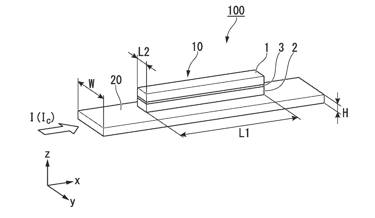
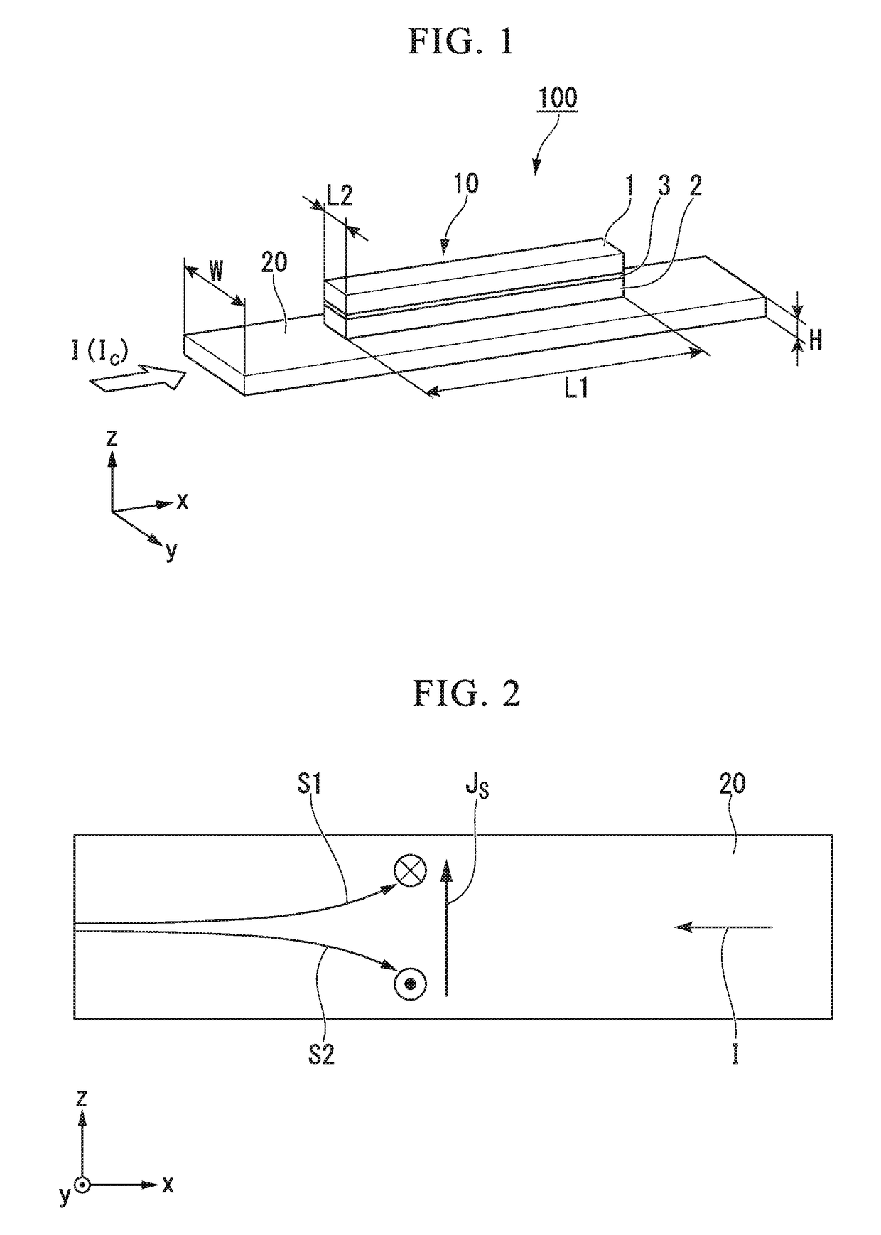
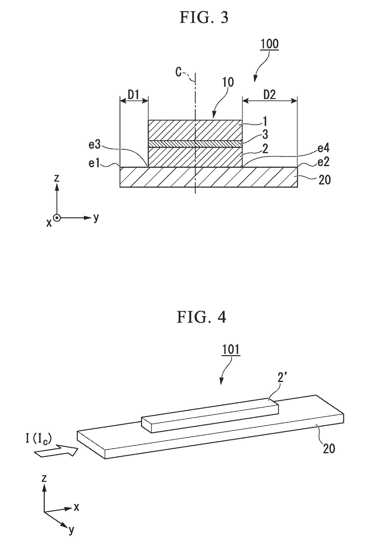
[0030]FIG. 1 is a perspective view schematically illustrating a spin-orbit torque type magnetization reversal element according to a first embodiment.

[0031]The spin-orbit torque type magnetization reversal element 100 according to the first embodiment has a magnetoresistance effect element 10 and spin-orbit torque wiring 20.

[0032]In the following description, the stacking direction of the magnetoresistance effect element 10 is deemed the z-direction, a first direction along which the spin-orbit torque wiring 20 extends is deemed the x-direction, a second direction which is orthogonal to both the x-direction and the z-direction is deemed the y-direction.

[0033]The magnetoresistance effect element 10 has a first ferromagnetic metal layer 1 having a fixed magnetization direction, a second ferromagnetic metal layer 2 having a variable magnetization direction, and a non-magnetic layer 3 sandwiched between the first ferromagnetic metal...

second embodiment

[0096]FIG. 5 is a perspective view schematically illustrating a spin-orbit torque type magnetization reversal element 102 according to a second embodiment. In the spin-orbit torque type magnetization reversal element 102 illustrated in FIG. 5, the shape of the spin-orbit torque wiring 21 is different from that in the spin-orbit torque type magnetization reversal element 100 according to the first embodiment. The remaining features are identical to those in the spin-orbit torque type magnetization reversal element 100 according to the first embodiment, and the same features are denoted by the same reference signs.

[0097]FIG. 6 is a schematic section view of the spin-orbit torque type magnetization reversal element 102 according to the second embodiment, when cut along the y-direction. In the spin-orbit torque type magnetization reversal element 102 illustrated in FIG. 6, the distance D1 between the first end portion e1 and the third end portion e3 is equal to the distance D2 between t...

third embodiment

[0104]FIG. 7 is a diagram schematically illustrating a spin-orbit torque type magnetization reversal element 103 according to a third embodiment. In the spin-orbit torque type magnetization reversal element 103 illustrated in FIG. 7, the configuration of the spin-orbit torque wiring 22 is different from that in the spin-orbit torque type magnetization reversal element 100 according to the first embodiment. The remaining features are identical to those in the spin-orbit torque type magnetization reversal element 100 according to the first embodiment, and the same features are denoted by the same reference signs.

[0105]FIG. 8 is a schematic section view of the spin-orbit torque type magnetization reversal element 103 according to the third embodiment, when cut along the y-direction.

[0106]In the spin-orbit torque type magnetization reversal element 103 illustrated in FIG. 8, the distance D1 between the first end portion e1 and the third end portion e3 is equal to the distance D2 between...


PUM


Abstract

A spin-orbit torque type magnetization reversal element including a ferromagnetic metal layer with a varying magnetization direction; and spin-orbit torque wiring that extends in a first direction intersecting with a stacking direction of the ferromagnetic metal layer and that is joined to the ferromagnetic metal layer; wherein when viewed from the first direction, the spin-orbit torque wiring is asymmetrical in a second direction that is orthogonal to the first direction and the stacking direction, with respect to an axis that passes through a center, in the second direction, of the ferromagnetic metal layer.

Description

BACKGROUND OF THE INVENTIONField of Invention[0001]The present invention relates to a spin-orbit torque type magnetoresistance reversal element, a magnetic memory, and high frequency magnetic device. Priority is claimed on Japanese Patent Application No. 2016-210534, filed Oct. 27, 2016, and Japanese Patent Application No. 2017-138386, filed Jul. 14, 2017, the contents of which are incorporated herein by reference.Description of Related Art[0002]Examples of known magnetoresistance effect elements include giant magnetoresistance (GMR) elements composed of a multilayer film of ferromagnetic layers and non-magnetic layers, and tunnel magnetoresistance (TMR) elements which use insulating layers (tunnel barrier layers, barrier layers) for the non-magnetic layers. Generally, TMR elements have a larger element resistance than GMR elements, but the magnetoresistance (MR) ratio is larger than GMR elements. Consequently, TMR elements are attracting much attention as elements for magnetic sens...

Claims


Application Information

Patent Timeline
IPC IPC(8): H01L43/04H01L43/08H01L43/10H01L43/14G11C11/16
CPCH01L43/04H01L43/08H01L43/10H01L43/14G11C11/161H10B61/00H10N50/10G11C11/18H10N50/80H10N52/80H10N50/85H10N52/01
Inventor SASAKI, TOMOYUKISHIOKAWA, YOHEI
Owner TDK CORPARATION
Learn More