
Hybrid circuit breaker having a bridge induction transfer structure

a transfer structure and hybrid technology, applied in the field of hybrid circuit breakers having induction transfer structures, can solve the problems of increasing complexity and cost, restricting its promotion and application, and hot issues, and achieve the effects of reducing the size and manufacturing cost of the circuit breakers, fast transfer speed, and reducing the size and cost of the capacitors

Active Publication Date: 2018-05-17
XI AN JIAOTONG UNIV
View PDF0 Cites 8 Cited by
  • Summary
  • Abstract
  • Description
  • Claims
  • Application Information

AI Technical Summary

Benefits of technology

The present invention describes a new circuit breaker design that uses a bridge structure and a capacitance and induction branch connected in series to quickly break the electrical current. This design reduces the size and manufacturing cost of the circuit breaker. By using an induction transfer module, the main loop capacitor doesn't need to be pre-charged, resulting in faster transfer speed and reduced size and cost of the capacitor. Additionally, the main loop capacitor only needs unidirectional charging, which improves its breaking reliability.

Problems solved by technology

A hybrid circuit breaker comprised of a high-speed mechanical switch and power semiconductor devices has advantages such as a large discharge capacity, a fast turn-off speed, and a strong current-limiting capability, and thus has become a hot issue to study in the field of breaking a large capacity system.
However, when breaking current using the full-control type power semiconductor device, its current transfer loop usually requires the full-control type power semiconductor device to switch off the current, consequently increasing complexity and cost, which restricts its promotion and application.
Without isolation, interference will occur to a charging power source and the main loop during a breaking process.
Moreover, it is highly demanding on voltage-withstanding capability of the main loop charging power supply, and the breaking is not reliable.

Method used


Image

  • Hybrid circuit breaker having a bridge induction transfer structure
  • Hybrid circuit breaker having a bridge induction transfer structure
  • Hybrid circuit breaker having a bridge induction transfer structure

Examples


Embodiment Construction

[0025]To enable those skilled in the art to better understand the solution of those skilled in the art, the technical solutions in the embodiments of the present disclosure will be described clearly and comprehensively in conjunction with FIGS. 1-11 in the embodiments of the present disclosure. Apparently, the embodiments described here are only part of embodiments of the present disclosure, instead of all embodiments. Based on the embodiments in the present disclosure, all other embodiments obtained by a person of normal skill in the art without exercise of inventive work should fall within the scope sought to protect in the present disclosure.

[0026]Hereinafter, the detailed description is only exemplary, not intended to limit application and usage. In addition, it is not intended to be subjected to any explicit or implicit theoretical restrictions presented in the Technical Field, Background, Summary, which are mentioned above, or the detailed depiction below. unless otherwise dep...


PUM


Abstract

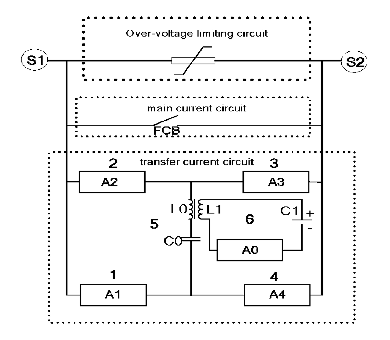
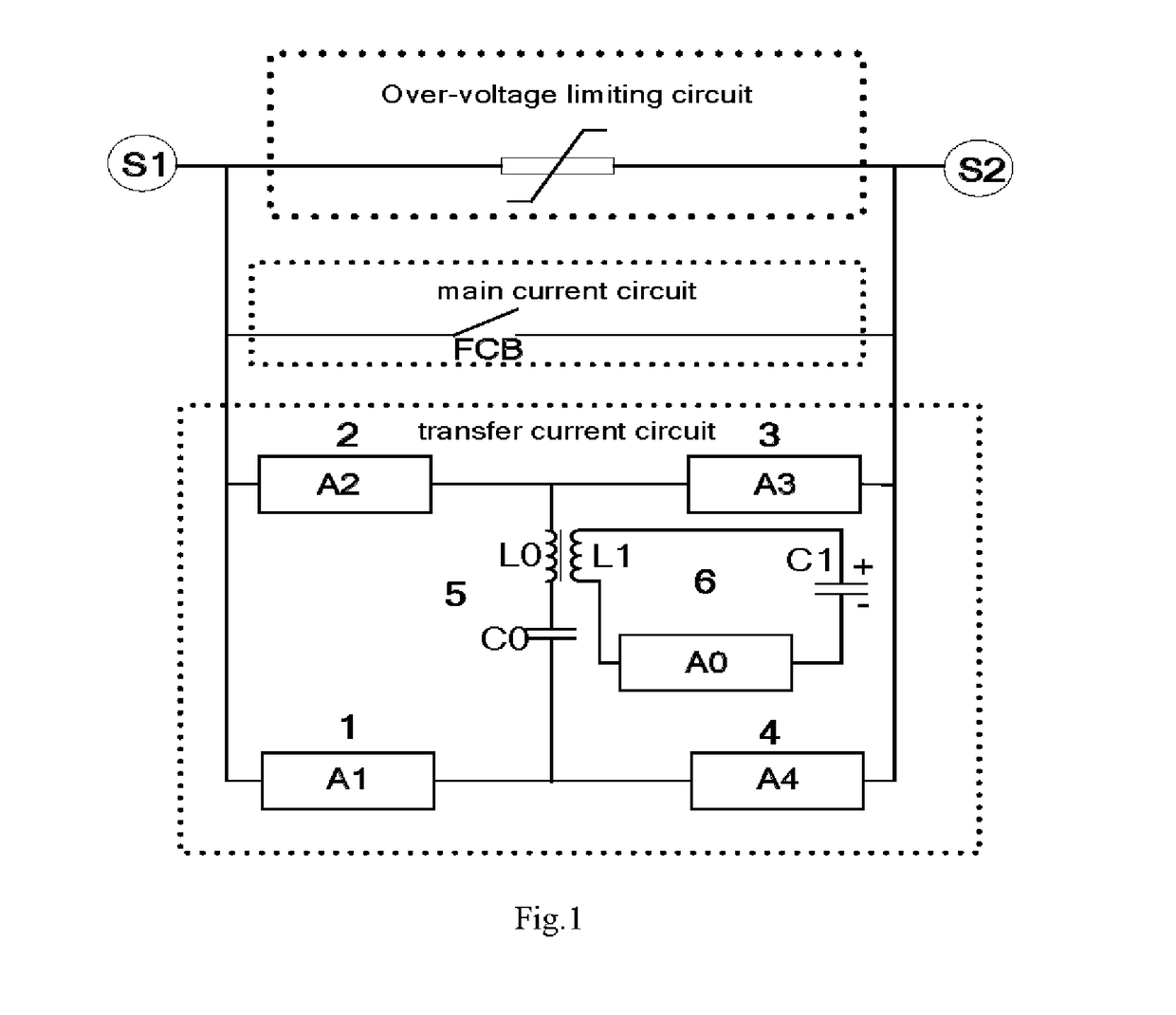
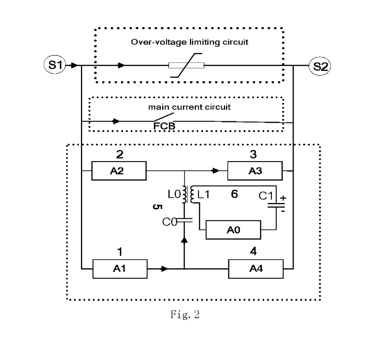
The present disclosure provides a hybrid circuit breaker having a bridge induction transfer structure, characterized in that the circuit breaker comprises a main current circuit, an over-voltage limiting circuit, and a transfer current circuit; and the main current circuit, the over-voltage limiting circuit, and the transfer current circuit are connected in parallel. The induction transfer circuit in the transfer current circuit comprises an induction transfer inductor, an induction transfer capacitor, and an induction transfer branch power semiconductor device which are connected in series; the transfer current circuit further comprises a bridge circuit comprised of a main loop capacitor; the main loop inductor and the induction transfer inductor are coupled to form a transformer. The present invention can implement fast breaking of the current, and effectively reduce the volume and manufacturing cost of the circuit breaker. With the induction transfer circuit, fast current transfer is implemented. The main loop capacitor needs no pre-charging. Isolation between the secondary charging circuit and the main loop is implemented. The transfer speed is fast, and the breaking reliability is high.

Description

FIELD OF THE INVENTION[0001]The present disclosure relates to the technical field of electronic devices, and more specifically to a transfer current circuit having a bridge induction transfer structure.BACKGROUND OF THE INVENTION[0002]A hybrid circuit breaker comprised of a high-speed mechanical switch and power semiconductor devices has advantages such as a large discharge capacity, a fast turn-off speed, and a strong current-limiting capability, and thus has become a hot issue to study in the field of breaking a large capacity system. Compared with other hybrid solutions, a hybrid DC circuit breaker scheme that uses a power semiconductor device with a full control function to break current has advantages such as a faster breaking speed and greater facilitation of breaking rational current. However, when breaking current using the full-control type power semiconductor device, its current transfer loop usually requires the full-control type power semiconductor device to switch off t...

Claims


Application Information

Patent Timeline
Patent Type & Authority Applications(United States)
IPC IPC(8): H02H3/02H01H9/54
CPCH01H9/542H02H3/02H02H3/087H02H9/04H01H33/596H01H2009/544H01H2009/543H01H9/548H01H33/14H02H3/08
Inventor YANG, FEIWU, YIRONG, MINGZHEWU, YIFEINIU, CHUNPING
Owner XI AN JIAOTONG UNIV
Learn More