Die edge integrity monitoring system

a technology of integrity monitoring and die edge, applied in the field of semiconductor/solid-state device testing/measurement, instruments, basic electric elements, etc., can solve the problems of small imperfections along the die edge giving rise to damages, cracks may further expand, and die edges may crack or otherwise become damaged

Active Publication Date: 2018-05-24
MELEXIS TECH NV
View PDF5 Cites 10 Cited by
  • Summary
  • Abstract
  • Description
  • Claims
  • Application Information

AI Technical Summary

Benefits of technology

[0009]It is an object of embodiments of the present invention to provide a good and reliable integrity monitoring system for detectio

Problems solved by technology

It is known that during the separation of semiconductor devices from the wafer the die edge may crack or otherwise become damaged during manufacturing.
It is also known that during the separation of the devices from the wafer, any small imperfection along the die edge may give rise to damages, for instance to cracks or other mechanical failures.
Even if these damages are small and do not reach the metallic layers of the chip, cracks might further expand during other manufacturing stages, or in qualification of the integrated circuit and handling, or during its lifetime, especially in thermally, mechanically or chemically harsh environments as for instance automotive applications.
The cracks may introduce defects in the structure and damage the metallization layers, as well as being a path for further damage if corrosive or harsh gasses and chemicals enter the cracks.
The function of the semiconductor device might be disturbed.
Thus, cracks and damages may produce a total failure of a semiconductor device, disturb its function, o

Method used


Image

  • Die edge integrity monitoring system
  • Die edge integrity monitoring system
  • Die edge integrity monitoring system

Examples


Embodiment Construction

[0038]The present invention will be described with respect to particular embodiments and with reference to certain drawings but the invention is not limited thereto but only by the claims. The drawings described are only schematic and are non-limiting. In the drawings, the size of some of the elements may be exaggerated and not drawn on scale for illustrative purposes. The dimensions and the relative dimensions do not correspond to actual reductions to practice of the invention.

[0039]The terms first, second and the like in the description and in the claims, are used for distinguishing between similar elements and not necessarily for describing a sequence, either temporally, spatially, in ranking or in any other manner. It is to be understood that the terms so used are interchangeable under appropriate circumstances and that the embodiments of the invention described herein are capable of operation in other sequences than described or illustrated herein.

[0040]Moreover, the terms top,...


PUM


Abstract

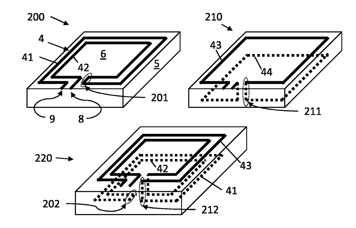
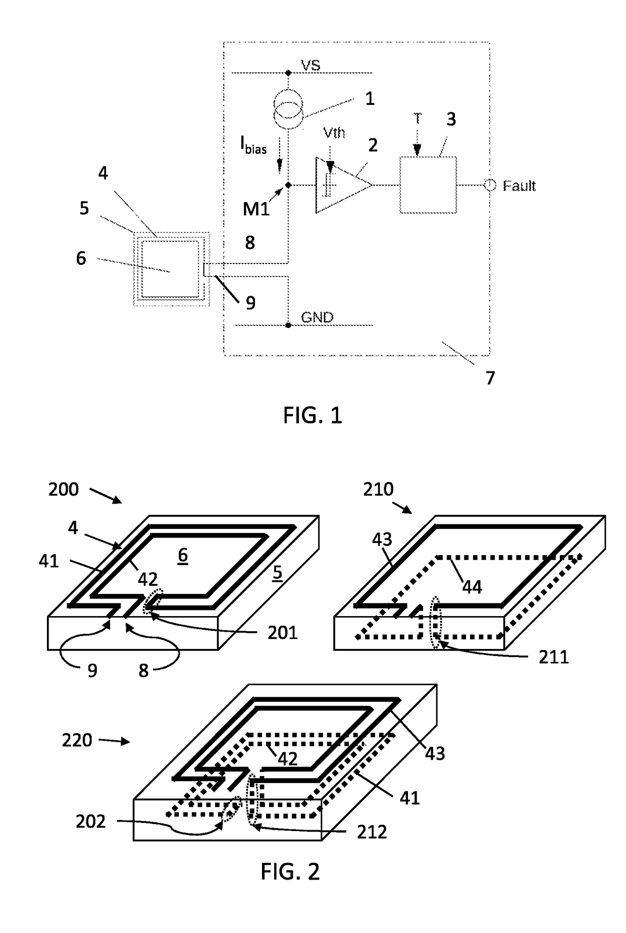
An edge crack monitoring system for an integrated circuit provided on a die, comprises a conductive trace comprising at least a first conductive path for allowing current in a first direction, and a second adjacent conductive path for allowing current in a second direction opposite to the first direction. Both adjacent conductive paths form at least one loop surrounding a semiconductor device on a die. The arrangement of the trace is adapted to provide compensation of EM interferences. The trace comprises two terminals being connectable to a detection circuit for detecting damages by generating a fault signal upon detection of disruption of the conductive trace due to a damage. The conductive trace comprises high resistance portions with a resistance of at least 1 kΩ, adapted for reducing self-resonance.

Description

FIELD OF THE INVENTION[0001]The invention relates to the field of semiconductor integrated electronics. More specifically it relates to methods and devices for monitoring and detection of damages in semiconductor die edges under the aspect of safety.BACKGROUND OF THE INVENTION[0002]During manufacture of integrated circuits, a semiconductor wafer is processed in order to provide a plurality of electronic chips. The number of chips, that a wafer can provide, depends of the area per chip and the total area of the wafer, which is dictated by industrial trends and technology. It is commercially important to obtain a high chip yield per wafer. However, the dice are required to be cut and separated. It is known that during the separation of semiconductor devices from the wafer the die edge may crack or otherwise become damaged during manufacturing. This may happen also during handling (e.g. during assembly in a larger circuit) or even during use, depending on the conditions and particular ...

Claims


Application Information

Patent Timeline
IPC IPC(8): H01L21/66H01L23/00G01R31/28
CPCH01L22/34H01L23/562G01R31/2896G01R31/2858H01L22/14H01L23/645H01L23/66H01L2223/6677
Inventor MUNDER, GUNNARGRIMM, HEIKOFREITAG, THOMAS
Owner MELEXIS TECH NV
Why Eureka
Try Eureka