Hybrid fuel system
a fuel system and hybrid technology, applied in the direction of machine/engine, engine controller, fuel injection control, etc., can solve the problem of the engine control unit (ecu) withdrawing liquid fuel volume, and achieve the effect of reducing nox emissions of the internal combustion engin
- Summary
- Abstract
- Description
- Claims
- Application Information
AI Technical Summary
Benefits of technology
Problems solved by technology
Method used
Image
Examples
first preferred embodiment
[0105]The present system preferably, though not essentially, provides for gaseous hydrogen to be supplied from a pressurised, exchangeable gas cylinder to a diesel engine. The supply of gaseous hydrogen is optional so that the engine remains operable on just its normal hydrocarbon fuel system. The engine may be a naturally aspirated or a turbocharged or supercharged engine.
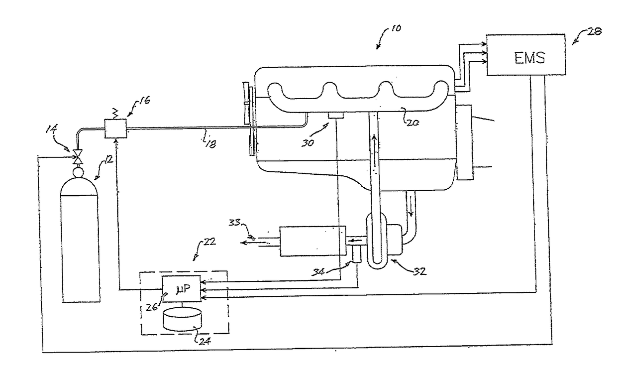
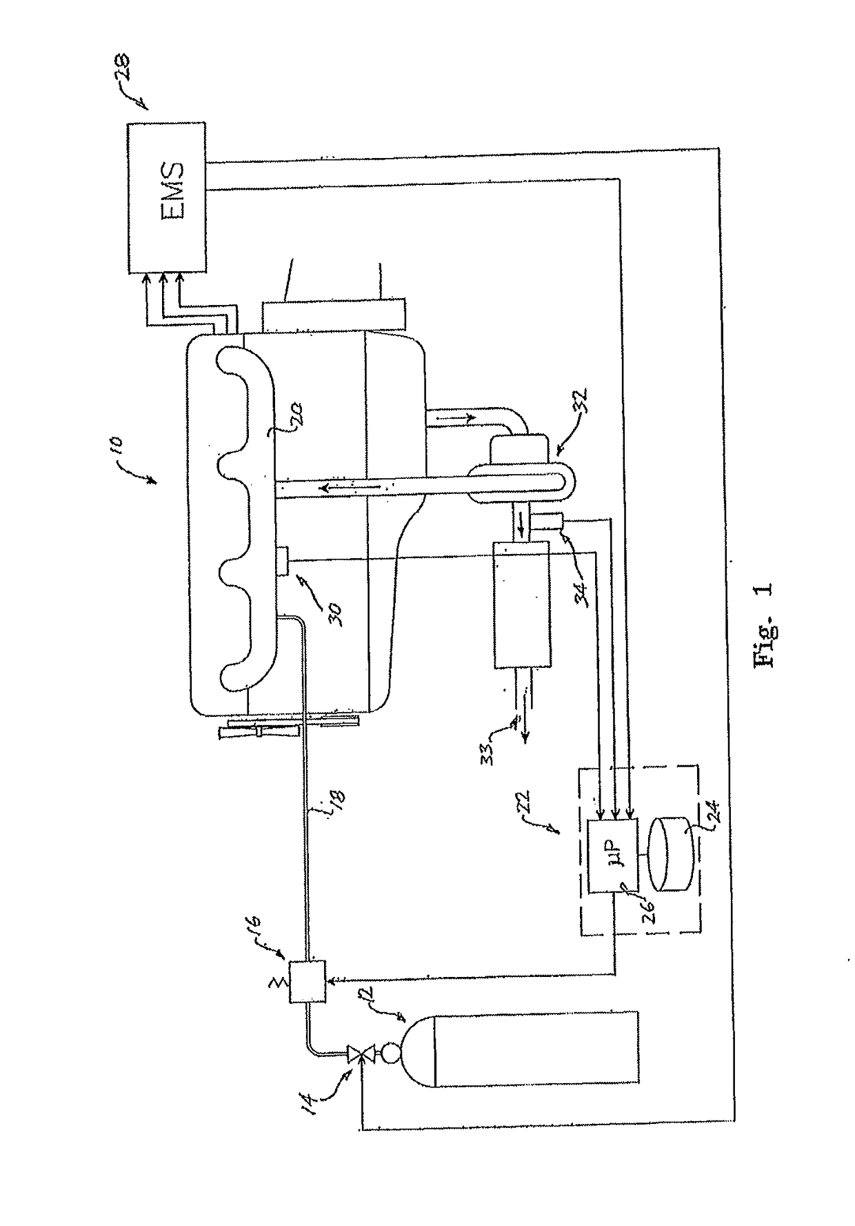
[0106]A preferred system of gaseous hydrogen delivery is shown in FIG. 1, in which a diesel engine 10, in this instance a turbocharged diesel engine, is provided with gaseous hydrogen from a pressurised gaseous hydrogen cylinder 12. A normally closed, solenoid shut-off valve 14, which may be under the control of an engine management system 16, opens the valve 14 only when the engine 10 is running.
[0107]Gaseous hydrogen supply to the engine 10 is preferably continuously modulated by means of an actuator operated, variable pressure regulator 18, controlled by a control module 20. Control module 20 comprises a microp...
second preferred embodiment
[0115]In this preferred embodiment with reference now to FIG. 2, the manner of delivery of gaseous hydrogen to the diffuser element 102 remains as described for the first embodiment above, but in this case the management of the pressure and flow of gaseous hydrogen to the diffuser 102 employs a different system.
[0116]As shown in FIG. 2, a gaseous hydrogen management system 100 according to this second preferred embodiment of the invention, provides for the supply of gaseous hydrogen to the diffuser 102, located within the air intake pipe 136 of a turbocharged diesel engine 110, at least at two different supply pressures. The supply of gaseous hydrogen to the engine 110 may again be optional by switching off the gaseous hydrogen supply system; that is the engine can be operated just with its normal hydrocarbon liquid fuel.
[0117]In a preferred arrangement, a primary supply of pressurized gaseous hydrogen is again provided in the form of one or more gas cylinders 106, preferably at 200...
third preferred embodiment
[0125]In a third preferred embodiment with reference to FIG. 1, a turbocharged diesel engine 10 is provided with a variable supply of gaseous hydrogen to supplement its normal hydrocarbon liquid fuel. The gaseous hydrogen is provided as a continuous supply when the engine is running, from a pressurized supply source in the form of an exchangeable pressurized supply cylinder 12, preferably pressurized to around 200 bar. The supply of gaseous hydrogen to the engine 10 is optional, in that it may be switched on or off as required, so that the engine may be operated in a liquid fuel only mode.
[0126]A solenoid controlled safety shut off valve 14 is located between the supply cylinder 12 and an actuator-controlled, variable pressure regulator 16, so as to prevent a dangerous build-up of hydrogen gas in the air intake manifold and in the engine when this is stationary. The shut off valve 14 is arranged to default to a closed state if the engine 10 is not running. The variable pressure regu...
PUM
 Abstract
Description
Claims
Application Information
 - R&D
- Intellectual Property
- Life Sciences
- Materials
- Tech Scout
- Unparalleled Data Quality
- Higher Quality Content
- 60% Fewer Hallucinations
Browse by: Latest US Patents, China's latest patents, Technical Efficacy Thesaurus, Application Domain, Technology Topic, Popular Technical Reports.
© 2025 PatSnap. All rights reserved.Legal|Privacy policy|Modern Slavery Act Transparency Statement|Sitemap|About US| Contact US: help@patsnap.com


