Eureka AIR delivers breakthrough ideas for toughest innovation challenges, trusted by R&D personnel around the world.

Motor drive device

Active Publication Date: 2018-06-21
FANUC CORP
View PDF3 Cites 5 Cited by
  • Summary
  • Abstract
  • Description
  • Claims
  • Application Information

AI Technical Summary

Benefits of technology

The present invention provides a motor drive device that can detect a decline in the capacitance of the DC link capacitor during initial charging and in individual sections of a multiple inverter system with a reverse converter and DC link capacitor. This helps to improve the efficiency and reliability of the motor drive device.

Problems solved by technology

However, since the conventional motor drive device 1X performs capacitance decline detection during the initial charging operation from when the electric charge of the DC link capacitor 22 is 0 C and the voltage is 0 V, in the case of the initial charging operation not being performed over a long time period, it is not possible to detect the capacitance decline of the DC link capacitor 22.

Method used


Image

  • Motor drive device
  • Motor drive device
  • Motor drive device

Examples


Embodiment Construction

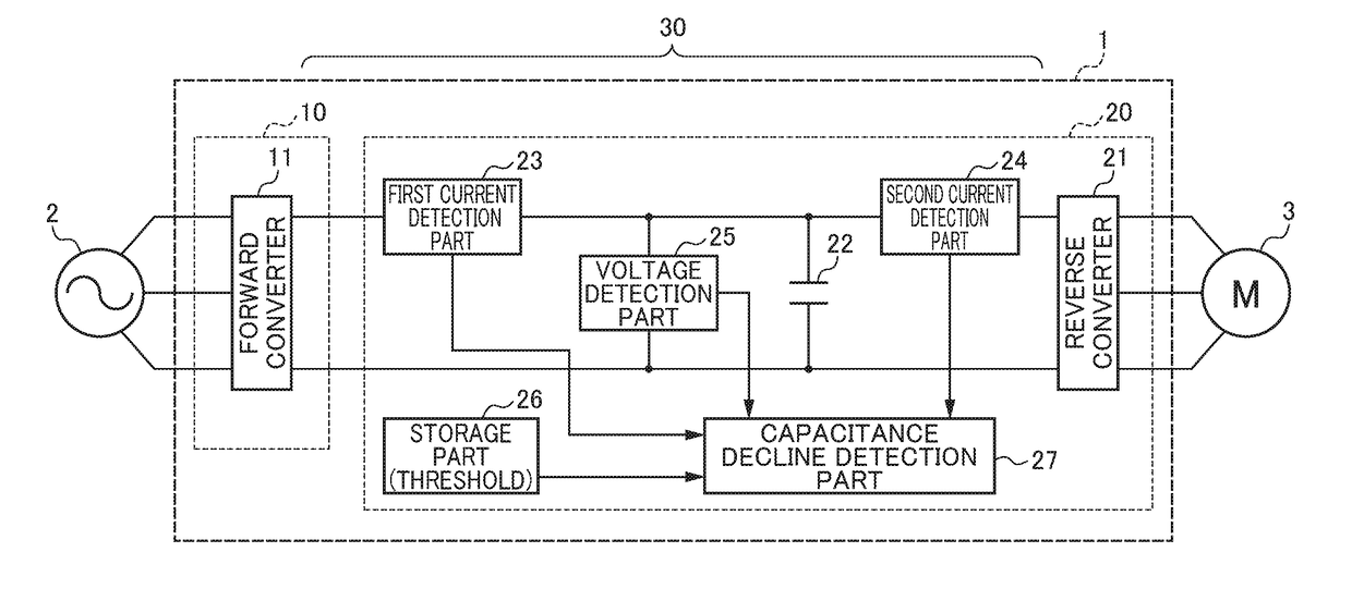
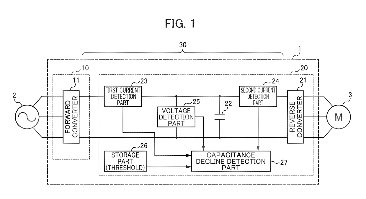
[0029]Hereinafter, an example of an embodiment of the present invention will be explained by referencing the drawings. It should be noted that the same reference symbols shall be attached to identical or corresponding portions in the respective drawings.

[0030]FIG. 1 is a view showing a circuit configuration of a motor drive device according to an embodiment of the present invention. A motor drive device 1 shown in FIG. 1 is inputted a commercial three-phase AC power source 2 to drive a motor 3. It should be noted that the AC power source 2 is not limited to three-phase alternating current, and may be single-phase alternating current, for example. The motor drive device 1 includes a converter section 10 and an inverter section 20.

[0031]The converter section 10 includes a forward converter 11. The forward converter 11 converts the AC power from the AC power source 2 into DC power. The forward converter 11, for example, is configured by a power semiconductor device and a diode rectifyi...


PUM


Abstract

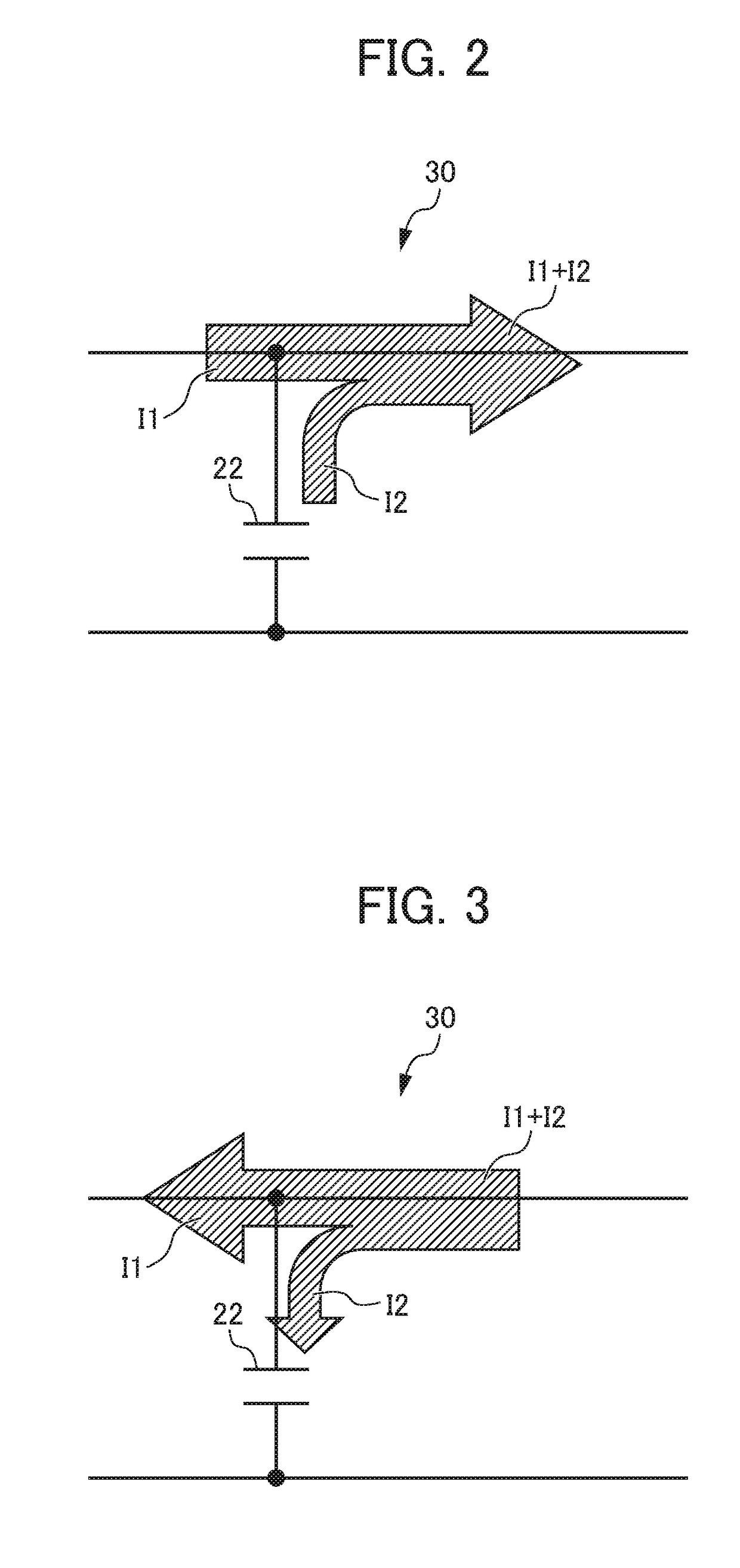
A motor drive device includes: reverse converter that converts DC power from a forward converter into AC power; a DC link capacitor provided in a DC link; a first current detection part that detects current flowing between the forward converter and capacitor; a second current detection part that detects current flowing between the capacitor and reverse converter; a voltage detection part that detects a voltage of the capacitor; and a capacitance decline detection part that obtains a change value in electric charge of the capacitor from a n integrated value by integrated a predetermined time of a difference in current values detected by the current detection parts, obtains a capacitance value of the capacitor based on the obtained change amount in electric charge and change amount in voltage of the capacitor for the predetermined time, and detects a capacitance decline in the capacitor based on the obtained capacitance value.

Description

[0001]This application is based on and claims the benefit of priority from Japanese Patent Application No. 2016-247958, filed on 21 Dec. 2016, the content of which is incorporated herein by reference.BACKGROUND OF THE INVENTIONField of the Invention[0002]The present invention relates to a motor drive device.Related Art[0003]A motor drive device has been known that drives the motors within machine tools, industrial machines, forge rolling machines, injection molding machines or various robots (for example, refer to Patent Documents 1 and 2). Such a motor drive device includes a forward converter that converts AC power to DC power, a reverse converter that converts the DC power from the forward converter into AC power, and a DC link capacitor provided to a DC link between the forward converter and reverse converter.[0004]However, the DC link capacitor may have a decline in electrostatic capacitance (hereinafter referred to simply as “capacitance”) due to the repeat of charge-discharge...

Claims


Application Information

Patent Timeline
IPC IPC(8): H02P27/06
CPCH02P27/06G01R27/2605H02M5/44H02M1/0003H02M1/0009H02P27/08
Inventor YOSHIDA, TOMOKAZU
Owner FANUC CORP
Why Eureka
Eureka Blog
Learn More