Feature based cooling using in wall contoured cooling passage

Active Publication Date: 2018-06-28
GENERAL ELECTRIC CO
View PDF8 Cites 24 Cited by
  • Summary
  • Abstract
  • Description
  • Claims
  • Application Information

AI Technical Summary

Problems solved by technology

Accordingly, in combination with manufacturing a liner from a high-temperature resistant material, effective cooling of the combustion liner wall and other components has become increasingly important and challenging.
Combustion liners and other components in the turbine may experience high temperature ar

Method used


Image

  • Feature based cooling using in wall contoured cooling passage
  • Feature based cooling using in wall contoured cooling passage
  • Feature based cooling using in wall contoured cooling passage

Examples


Embodiment Construction

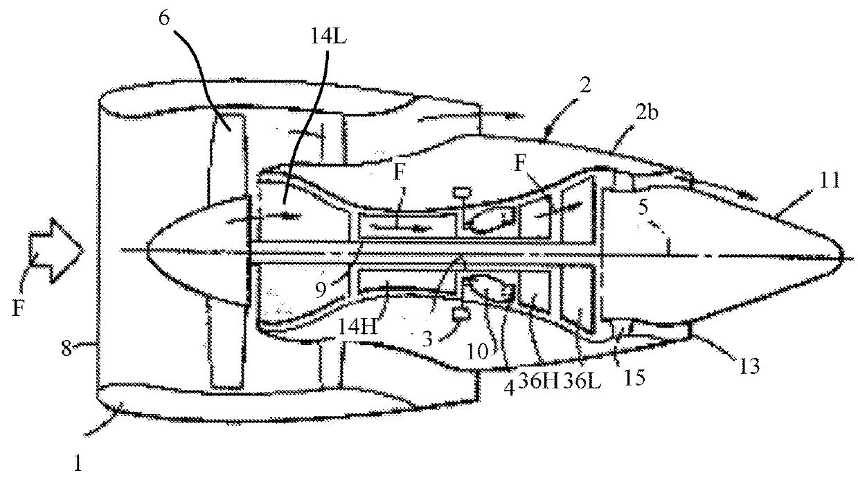
[0022]As shown in FIG. 1, an example of a turbine gas engine may be a turbofan engine that is symmetric about an axis 5. The engine may include a casing 1 having an inlet 8, a bay 2, a fan 6, a low pressure compressor portion 14L, and a high pressure compressor portion 14H. The engine may further include a combustor 10, having a fuel inlet 3 and an exit 4. The compressed air F flowing through the compressor and having traveled though the combustor 10 is expanded through the high pressure turbine portion 36H and low pressure turbine portion 36L. At least one of the turbine portions drive both the fan 6 and compressor portions through at least one shaft 9. The flow F traveling though the engine may exit at a fan exit, a bay exit 2b and / or at the exhaust exit 13, traveling over tail portion 11.

[0023]While the majority of the description above describes a component in a turbofan type turbine, the above disclosure is intended as an example and not as an exclusive description. The followi...


PUM


Abstract

A combustion liner or component produced through the use of additive manufacturing techniques. The combustion liner or other component may be formed having a feature based optimized cooling circuit at least partially embedded in the thickness of the material. The internal cooling circuit, may be used, along with other benefits, to control the temperature of the component and prevent hot-spots and uneven heat distribution across the surface of the component.

Description

INTRODUCTION[0001]The disclosure relates to improved cooling designs for engine components that include at least one internal bore passage formed in a solid material or substrate within an engine. The disclosure provides cooling passages optimized to provide for one or more of the following characteristics: thermo-mechanical load carrying capability, cooling and / or temperature control, improved temperature gradient, and improved life of component.BACKGROUND[0002]Gas turbine engines generally include at least one compressor to pressurize air to be channeled into a combustor, the engine may include at least one combustor in which at least a portion of the channeled pressurized air is mixed with fuel and ignited, the hot gasses from the compressor flow downstream through at least one turbine section. Each turbine section has rotating blades rotating about an axis and contained within an engine housing. The turbine section or sections may power any one of the compressor, a fan, a shaft,...

Claims


Application Information

Patent Timeline
IPC IPC(8): F02C7/12F23R3/00
CPCF02C7/12F23R3/002F05D2260/20F05D2230/30F23R3/005F23R3/06F23R2900/00018F01D5/186F01D5/187F01D5/288F01D25/12
Inventor WERTZ, AARON
Owner GENERAL ELECTRIC CO
Why Eureka
Try Eureka