Thermally conductive structure and heat dissipation device

a technology of thermal conductivity and heat dissipation device, which is applied in the direction of conduction heat transfer modification, semiconductor/solid-state device details, lighting and heating apparatus, etc. it can solve the problems of inability to meet the needs of light weight and thinness in modern thinned electronic products, the electronic components of electronic devices will inevitably produce more heat than the conventional electronic components, and the radiator is too bulky to meet the need of light weight and thinness. , to achieve the

Inactive Publication Date: 2018-07-05
JIANGSU CNANO TECHNOLOGY CO LTD
View PDF3 Cites 11 Cited by
  • Summary
  • Abstract
  • Description
  • Claims
  • Application Information

AI Technical Summary

Benefits of technology

[0019]As such, in the thermally conductive structure and heat dissipation device of the invention, the first thermally conductive layer comprises the plurality of first carbon nanotubes dispersed in the graphene material, and the second thermally conductive layer is stacked on the first thermally conductive layer and comprises the plurality of second carbon nanotubes dispersed in the porous material. With the structure of the first thermally conductive layer and second thermally conductive layer, the heat generated by the heat source can be rapidly conducted and then dissipated, and also the thermally conductive structure and heat dissipation device have the feature of thinness and meet the need of thinness in modern electronic products.

Problems solved by technology

In the case of high-speed operation, the electronic components of electronic devices will inevitably produce more heat than the conventional electronic components.
The high temperature operating environment may affect the characteristics of electronic components, and ultrahigh temperature is more likely to cause permanent damage to electronic components.
However, for the heat dissipation device mentioned above, the radiator is too bulky to meet the need of light weight and thinness in the modern thinned electronic products.
How to provide a thermally conductive structure and heat dissipation device, which have better thermal conduction effect and thinness feature and meet the need of light weight and thinness in the modern thinned electronic products, has become an important issue.

Method used


Image

  • Thermally conductive structure and heat dissipation device
  • Thermally conductive structure and heat dissipation device
  • Thermally conductive structure and heat dissipation device

Examples


Embodiment Construction

[0026]The thermally conductive structure and heat dissipation device according to the preferred embodiments of the prevention invention will be described in connection with the related drawings and figures, in which like elements are indicated by like numerals.

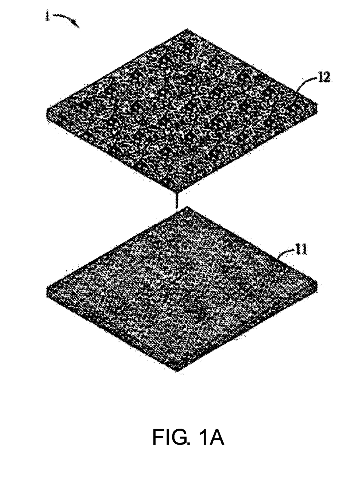
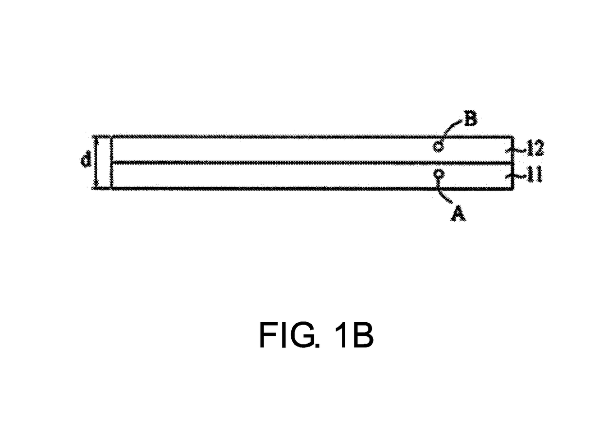
[0027]Referring to FIG. 1A to FIG. 1D, in which FIG. 1A and FIG. 1B are exploded schematic view and schematic view of a thermally conductive structure 1 according to an preferred embodiment of the prevention invention, respectively, and FIG. 1C and FIG. 1D are enlarged schematic views of regions A and B of FIG. 1B, respectively. Accordingly, FIG. 1C and FIG. 1D are merely indicative and not drawn according to the scale of actual elements.

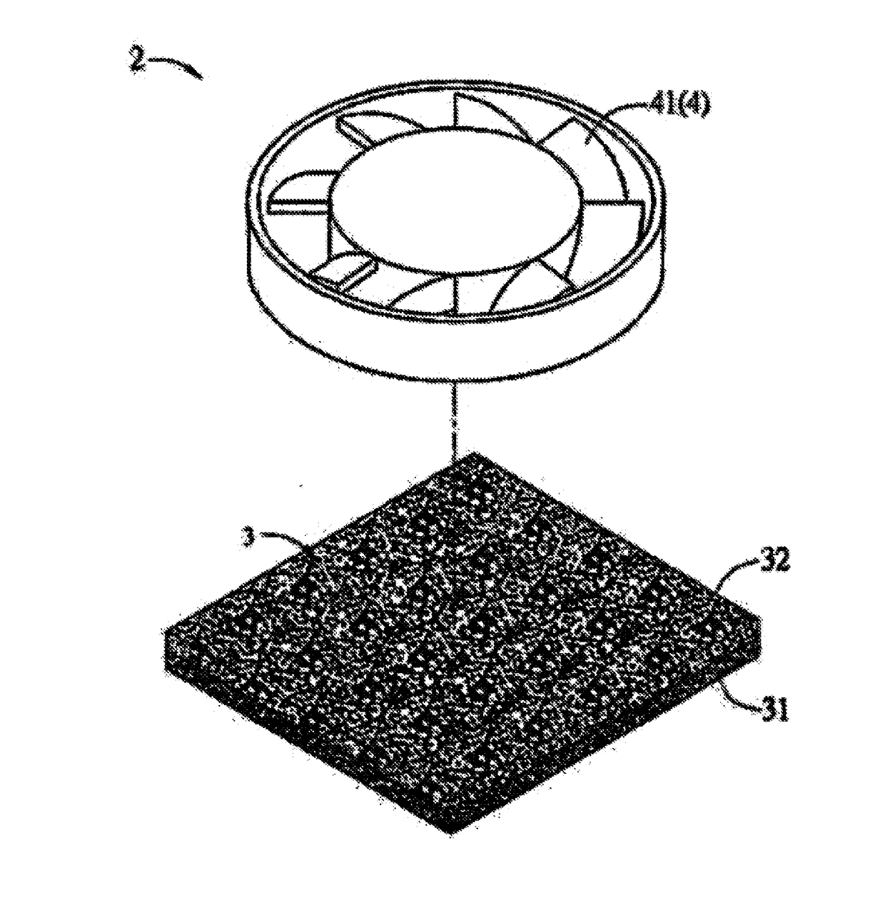
[0028]The thermally conductive structure 1 can rapidly conduct the heat generated by a heat source (such as an electronic component) and comprises a first thermally conductive layer 11 and a second thermally conductive layer 12, and the first thermally conductive layer 11 and a second thermall...


PUM

PropertyMeasurementUnit
thicknessaaaaaaaaaa
particle sizeaaaaaaaaaa
diameteraaaaaaaaaa

Abstract

A thermally conductive structure and a heat dissipation device are provided. The thermally conductive structure comprises a first thermally conductive layer and a second thermally conductive layer. The first thermally conductive layer comprises a graphene material and first carbon nanotubes, and the first carbon nanotubes are dispersed in the graphene material. The second thermally conductive layer is stacked on the first thermally conductive layer, and comprises a porous material and second carbon nanotubes, and the second carbon nanotubes are dispersed in the porous material. The heat dissipation device comprises the thermally conductive structure and a heat dissipation structure. The thermally conductive structure is in contact with a heat source, and the heat dissipation structure is connected to the thermally conductive structure. The thermally conductive structure and the heat dissipation device are characterized by thinness, and meet the need of light weight and thinness in modern thinned electronic products.

Description

CROSS-REFERENCE TO RELATED APPLICATION[0001]This is a continuation of International Application No. PCT / CN2016 / 000467, filed on Aug. 18, 2016, which claims the priority benefits of China Application No. 201510549129.2, filed on Aug. 31, 2015. The entirety of each of the above-mentioned patent applications is hereby incorporated by reference herein and made a part of this specification.BACKGROUNDTechnical Field[0002]The present invention relates to a thermally conductive structure and heat dissipation device, in particular to a thinned thermally conductive structure and heat dissipation device.Description of Related Art[0003]With the development of science and technology, thinness and high efficiency are the consideration for the design and development of electronic devices. In the case of high-speed operation, the electronic components of electronic devices will inevitably produce more heat than the conventional electronic components. The high temperature operating environment may a...

Claims


Application Information

Patent Timeline
Patent Type & Authority Applications(United States)
IPC IPC(8): F28F21/02F28F3/00F28D15/02
CPCF28F21/02H05K7/2039H05K7/20136F28F3/00F28D2021/0029F28F13/003H01L23/373H01L23/3731H01L23/3736H01L23/3737H05K7/20181H05K7/20481H05K7/20172H05K7/20336
Inventor CAI, WEIZHENGYANG, ZHIWEIZHENG, TAOMAO, OUZHANG, MEIJIE
Owner JIANGSU CNANO TECHNOLOGY CO LTD
Why Eureka
Try Eureka