Electrostatic chuck heater

a heater and electric chuck technology, applied in the direction of ohmic-resistance heating, ohmic-resistance heating details, electric discharge tubes, etc., can solve the problems of insufficient heat generation amount of the heater in a zone including a cool spot, inability to apply, and insufficient temperature, so as to reduce resistance and reduce resistance. the effect of large width and reduced resistan

Active Publication Date: 2018-07-05
NGK INSULATORS LTD
View PDF1 Cites 7 Cited by
  • Summary
  • Abstract
  • Description
  • Claims
  • Application Information

AI Technical Summary

Benefits of technology

[0007]In this electrostatic chuck heater, the small-zone formation region is provided inside the ceramic sintered body in which the electrostatic electrode is embedded or the heater support body that is integrated with the ceramic sintered body. The small-zone formation region includes the plurality of small zones in which the small heater electrodes are wired. In addition, the plurality of small heater electrodes are connected in parallel to the power source. Electric power supplied to each of the small heater electrodes is supplied from the power source by using the output ratio to the suppliable output corresponding to each of the small heater electrodes. Such an output ratio may be, for example, if a power source with a constant voltage is connected to the heater via a switch, a ratio τ / T (duty ratio) of a period τ during which the switch is turned on to a period T. Here, the resistance of the small heater electrode wired in the small zone including a cool spot is set to a smaller value than that of the other small heater electrodes. Since the plurality of small heater electrodes are connected in parallel to the power source, the amount of heat that can be generated by each of the small heater electrodes is increased as the resistance is decreased. Although it is not possible to supply electric power that is over the upper limit of the output ratio to the small heater electrode in the small zone including a cool spot, since the resistance is lower than that of the small heater electrodes in the other zones, the heat generation amount is increased even if the output ratio is the same. Accordingly, it is possible to ensure a margin for electric power that is applicable to each small heater in a state in which the temperature of the zone including a cool spot is the same or substantially the same as the temperature of the zones not including a cool spot. Thus, it is possible to make the temperature sufficiently equal in the electrostatic chuck heater of a multi-zone heater type against variable temperatures due to various disturbances.
[0008]In the electrostatic chuck heater of the present invention, the small heater electrode that is wired in the small zone including the cool spot may have a larger width than the other small heater electrodes or may be formed of a material having a lower resistivity than that of the other small heater electrodes. Even if the electrode material is the same, a large width decreases the resistance. In addition, even if the width is the same, the use of a material having a low resistivity decreases the resistance. Thus, in this manner, the present invention can be easily implemented.

Problems solved by technology

However, there is an upper limit of applicable electric power under the restriction of the resistance of the heaters and a power source capacity, and accordingly, it is not possible to apply, to the heater in a zone including a cool spot, electric power that is over the upper limit of the applicable electric power.
Therefore, in some cases, the heat generation amount of the heater in a zone including a cool spot has been insufficient, and the temperature has not been sufficiently equal.
Although it is not possible to supply electric power that is over the upper limit of the output ratio to the small heater electrode in the small zone including a cool spot, since the resistance is lower than that of the small heater electrodes in the other zones, the heat generation amount is increased even if the output ratio is the same.

Method used


Image

  • Electrostatic chuck heater
  • Electrostatic chuck heater
  • Electrostatic chuck heater

Examples


Embodiment Construction

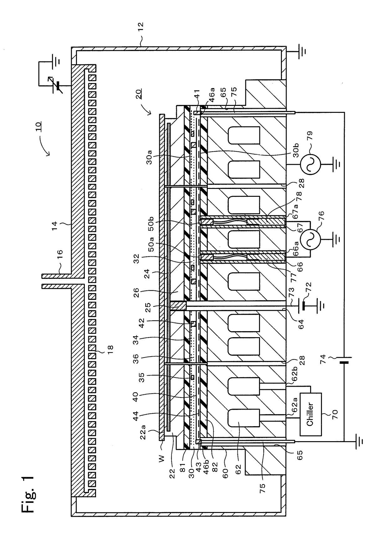
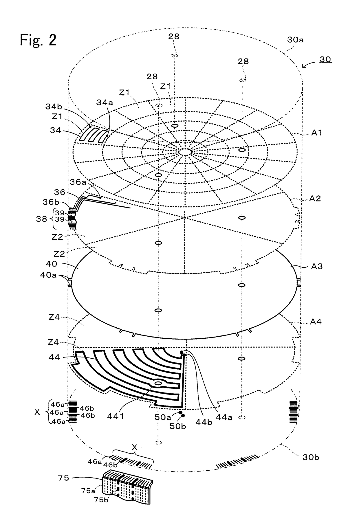
[0015]A preferred embodiment of the present invention will be described below with reference to the drawings. FIG. 1 is a cross-sectional view illustrating a general configuration of a plasma processing apparatus 10, and FIG. 2 is a perspective view illustrating an internal structure of a sheet heater 30.

[0016]The plasma processing apparatus 10, which is a semiconductor manufacturing apparatus, includes a vacuum chamber 12, a shower head 14, and an electrostatic chuck heater 20, as illustrated in FIG. 1. The vacuum chamber 12 is a container formed to have a box shape by using an aluminum alloy or the like. The shower head 14 is provided on a ceiling surface of the vacuum chamber 12. The shower head 14 emits a process gas supplied through a gas introduction pipe 16, from a large number of gas injection holes 18, to the inside of the vacuum chamber 12. In addition, the shower head 14 plays a role of a cathode plate for generating plasma. The electrostatic chuck heater 20 is an apparat...


PUM


Abstract

An electrostatic chuck heater includes an electrostatic chuck in which an electrostatic electrode is embedded in a ceramic sintered body; a small-zone formation region including a plurality of small zones in which small heater electrodes are wired; a power source to which the plurality of small heater electrodes are connected in parallel; and a small-zone control apparatus that performs control such that desired electric power is supplied to each of the small heater electrodes, wherein among the plurality of small heater electrodes, a small heater electrode that is wired in a small zone including a cool spot has a resistance that is set to a smaller value than that of the other small heater electrodes.

Description

BACKGROUND OF THE INVENTION1. Field of the Invention[0001]The present invention relates to an electrostatic chuck heater.2. Description of the Related Art[0002]In semiconductor manufacturing apparatuses, ceramic heaters for heating wafers are employed. As such a ceramic heater, a so-called multi-zone heater is known. In this heater, an inner circumferential heater and an outer circumferential heater that are made of a high-melting point metal are embedded respectively in an internal zone and an external zone in a ceramic base, and electric power is supplied independently to each of the heaters, and thereby heat generation of each of the heaters is independently controlled (see, for example, PTL 1).CITATION LISTPatent Literature[0003]PTL 1: JP 2007-88484 ASUMMARY OF THE INVENTION[0004]In order to independently control the heat generation of each of the heaters in such a multi-zone heater, it is conceivable to individually control the electric power of each of the heaters. In this cas...

Claims


Application Information

Patent Timeline
Patent Type & Authority Applications(United States)
IPC IPC(8): H01L21/683H01L21/67H01J37/32H05B3/03
CPCH01L21/6833H01L21/67103H01J37/32724H05B3/03H01L21/67109H01L21/6831H05B3/283H05B2203/003H05B1/0233H05B3/18
Inventor TAKEBAYASHI, HIROSHIHIRATA, NATSUKIHASEGAWA, SHINYA
Owner NGK INSULATORS LTD
Why Eureka
Try Eureka